Getting a old printer motor to work-With over two decades of expertise troubleshooting printers and copiers, I’ve encountered countless machines loaded with motors. The intricacies of how these motors functioned were often straightforward: either they worked, or they didn’t. In cases where they didn’t, the solution was often to discard the malfunctioning unit; if they did, the issue lay elsewhere. Throughout this extensive period, I’ve encountered and worked with hundreds of outrunner motors. Distinguished by the unique characteristic of the motor body spinning, not just the shaft, these motors offer a unique combination of low speed and high torque. Their strength lies in their ability to efficiently maneuver challenging components such as developer tanks or drums within printers. For my latest venture, the Facehugger project, I’ve salvaged one of these outrunner motors from an HP color printer. Beyond being low-profile, it boasts ample power to bring my facehuggers to life through animation. However, one hurdle stands in the way: the peculiar pinout configuration of the motor. While the markings +24 and GND align logically, the subsequent labels—F/R (presumably for forward and reverse), ACC, DEC, and MFG—present a puzzle. Deciphering their functions isn’t straightforward. If you’ve stumbled upon this blog through a Google search, I hope you find the answers you seek. Personally, my breakthrough came from a stroke of luck during an eBay auction, as these details proved elusive elsewhere in my quest. In my test, I simply tied ACC and F/R to ground then applied PWM to the DEC using an UNO and the code below. This code uses a potentiometer to alter the PWM signal to increase and decrease the speed of the motor. MFG is not connected. If your project has a metal frame I would assume you connect this to your metal frame to reduce noise.
With over two decades of expertise troubleshooting printers and copiers, I’ve encountered countless machines loaded with motors. The intricacies of how these motors functioned were often straightforward: either they worked, or they didn’t. In cases where they didn’t, the solution was often to discard the malfunctioning unit; if they did, the issue lay elsewhere.
Throughout this extensive period, I’ve encountered and worked with hundreds of outrunner motors. Distinguished by the unique characteristic of the motor body spinning, not just the shaft, these motors offer a unique combination of low speed and high torque. Their strength lies in their ability to efficiently maneuver challenging components such as developer tanks or drums within printers.
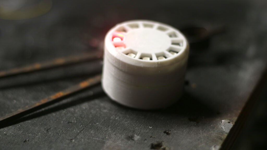
For my latest venture, the Facehugger project, I’ve salvaged one of these outrunner motors from an HP color printer. Beyond being low-profile, it boasts ample power to bring my facehuggers to life through animation.
However, one hurdle stands in the way: the peculiar pinout configuration of the motor. While the markings +24 and GND align logically, the subsequent labels—F/R (presumably for forward and reverse), ACC, DEC, and MFG—present a puzzle. Deciphering their functions isn’t straightforward. If you’ve stumbled upon this blog through a Google search, I hope you find the answers you seek. Personally, my breakthrough came from a stroke of luck during an eBay auction, as these details proved elusive elsewhere in my quest.
F/R is indeed forward and reverse.
ACC needs to go low, this is possibly “active”. When this goes low the motor can drive.
DEC is the pin for your PWM (pulse width modulation) or how fast you want your motor to spin.
MFG is motor frame ground from what I understand.
In my test, I simply tied ACC and F/R to ground then applied PWM to the DEC using an UNO and the code below.
#include <TimerOne.h>

const int ledPin = 9;  // PWM capable pin for LED

void setup() {
  pinMode(ledPin, OUTPUT);

  // Set the desired PWM frequency (in Hz)
  Timer1.initialize(1000);  // 1 kHz
  Timer1.pwm(9, 512);  // 50% duty cycle, you can adjust as needed
}

void loop() {
  // Your main code here
}
This code uses a potentiometer to alter the PWM signal to increase and decrease the speed of the motor. MFG is not connected. If your project has a metal frame I would assume you connect this to your metal frame to reduce noise.
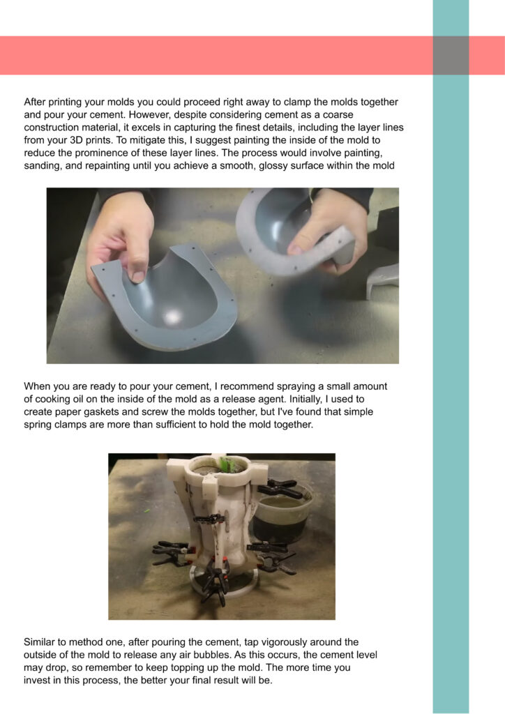
Spider dropper and 3D mold eBooks-If you prefer diving into the world of making through reading, I’ve got you covered with two comprehensive eBooks. Spider Dropper Project: You may already know about the Spider Dropper guide available on Hackaday and Instructables. But if you’re hungry for a deeper dive into this project, my eBook has you covered. Whether you’re a seasoned Arduino expert or a complete beginner, this guide will help you get started and take your Spider Dropper project to the next level. Creating 3D-Printed Reusable Molds for Casting Cement: Looking to venture into the fascinating world of 3D printing and cement casting? My eBook on this subject is your ultimate resource. Even if you’re starting from scratch with no prior Fusion360 knowledge, this guide will walk you through the process step by step, helping you become proficient in no time. You can find the books here: https://www.patreon.com/jwinfield/shop or the related videos here https://youtu.be/XWuaHZWFXcw or https://youtu.be/xxUgRfLmbrA
If you prefer diving into the world of making through reading, I’ve got you covered with two comprehensive eBooks.
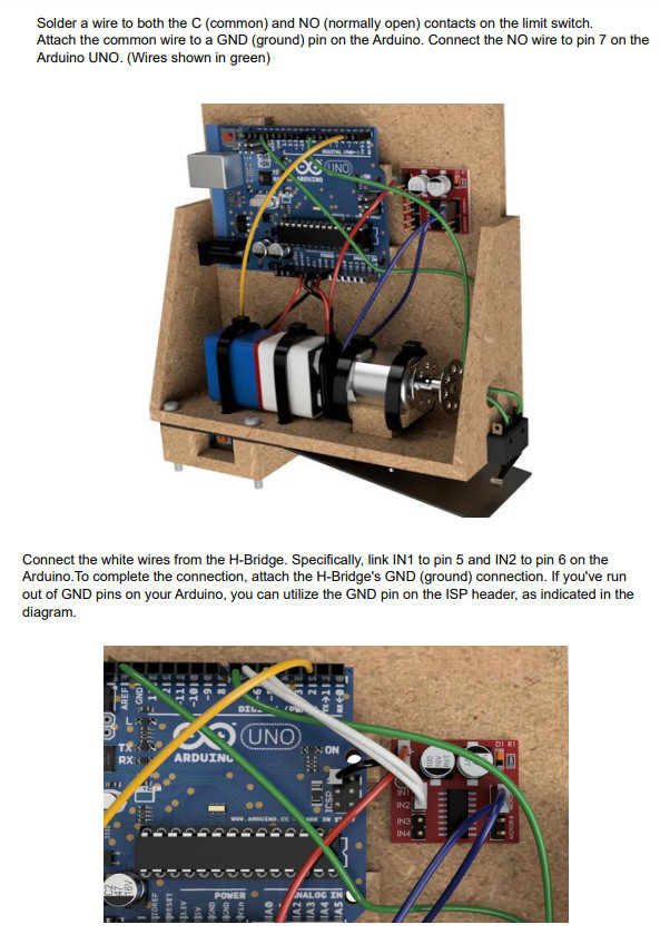
Spider Dropper Project: You may already know about the Spider Dropper guide available on Hackaday and Instructables. But if you’re hungry for a deeper dive into this project, my eBook has you covered. Whether you’re a seasoned Arduino expert or a complete beginner, this guide will help you get started and take your Spider Dropper project to the next level. Creating 3D-Printed Reusable Molds for Casting Cement: Looking to venture into the fascinating world of 3D printing and cement casting? My eBook on this subject is your ultimate resource.
Arduino Nano and MPU6050: A Tilt Sensing Adventure-Welcome to another exciting journey in the world of Arduino! In this blog post, we will explore how to use an Arduino Nano and an MPU6050 sensor to create a tilt sensor. We’ll discuss the hardware used, the theory of operation, and potential applications for this versatile sensor setup. Hardware Used Arduino Nano The Arduino Nano is a compact and popular microcontroller board based on the ATmega168microcontroller. It’s known for its small form factor, making it ideal for projects with limited space. MPU6050 The MPU6050 is an Inertial Measurement Unit (IMU) that combines a 3-axis accelerometer and a 3-axis gyroscope in a single module. It’s commonly used for motion and orientation sensing in a variety of projects. Neopixel ring (12) Theory of Operation What’s Tilt Sensing? Tilt sensing, also known as inclination sensing, is the ability to detect the orientation or angle of an object concerning the Earth’s gravitational field. This information is invaluable in various applications, from gaming controllers to robotics and even aerospace. MPU6050: The Brains Behind the Operation The MPU6050 IMU is the heart of our tilt sensor. It works based on the following principles: Our code combines data from the accelerometer and gyroscope to compute the orientation of the sensor, enabling us to detect tilting. Theory of Operation The Arduino Nano and MPU6050 tilt sensor code is designed to detect the orientation of the sensor and indicate if it’s level or tilted. Here’s how it works: Potential Uses 1. Digital Level You can use the Arduino Nano and MPU6050 setup as a digital level for applications like construction, carpentry, or any project requiring precise leveling. 2. Gaming Controllers The MPU6050 is a fundamental component in motion-based gaming controllers. You can create your own gamepad or input device for interactive experiences. 3. Robot Stabilization Tilt sensing is crucial in robotics. Your tilt sensor can be integrated into robots to ensure stability and control in various terrains. 4. Virtual Reality (VR) Headsets In VR applications, detecting the orientation of the headset is vital for creating immersive experiences. The MPU6050 can be part of your DIY VR projects. 5. Drone Stabilization Drones rely on IMUs like the MPU6050 for accurate flight control and stability. You can build your own drone or enhance an existing one. Conclusion The Arduino Nano and MPU6050 combination provides an excellent platform for tilt sensing. Whether you’re building a digital level, gaming controller, robot, or any other project requiring orientation detection, this versatile setup can be a valuable addition to your toolbox. By understanding the theory of operation and exploring potential uses, you can unlock endless possibilities for your maker projects. So, grab your Arduino Nano and MPU6050, and start building your own tilt sensor today!
Welcome to another exciting journey in the world of Arduino! In this blog post, we will explore how to use an Arduino Nano and an MPU6050 sensor to create a tilt sensor. We’ll discuss the hardware used, the theory of operation, and potential applications for this versatile sensor setup.
Hardware Used
Arduino Nano
The Arduino Nano is a compact and popular microcontroller board based on the ATmega168microcontroller. It’s known for its small form factor, making it ideal for projects with limited space.
MPU6050
The MPU6050 is an Inertial Measurement Unit (IMU) that combines a 3-axis accelerometer and a 3-axis gyroscope in a single module. It’s commonly used for motion and orientation sensing in a variety of projects.
Neopixel ring (12)
Theory of Operation
What’s Tilt Sensing?
Tilt sensing, also known as inclination sensing, is the ability to detect the orientation or angle of an object concerning the Earth’s gravitational field. This information is invaluable in various applications, from gaming controllers to robotics and even aerospace.
MPU6050: The Brains Behind the Operation
The MPU6050 IMU is the heart of our tilt sensor. It works based on the following principles:
Accelerometer: The accelerometer measures linear acceleration, including the force of gravity. This allows us to determine the tilt or inclination of the sensor in any direction.
Gyroscope: The gyroscope detects angular velocity, providing information about how fast the sensor is rotating.
Our code combines data from the accelerometer and gyroscope to compute the orientation of the sensor, enabling us to detect tilting.
Theory of Operation
The Arduino Nano and MPU6050 tilt sensor code is designed to detect the orientation of the sensor and indicate if it’s level or tilted. Here’s how it works:
Hardware: The setup consists of an Arduino Nano and an MPU6050 sensor. The MPU6050 is an Inertial Measurement Unit (IMU) that contains a 3-axis accelerometer and a 3-axis gyroscope. This hardware combination allows us to sense both linear acceleration and angular velocity.
Data Fusion: The code reads data from the MPU6050, specifically the accelerometer and gyroscope data. The accelerometer provides information about the sensor’s orientation concerning gravity, while the gyroscope detects how fast the sensor is rotating.
Determining Tilt: The code calculates the pitch and roll angles based on the accelerometer data. These angles represent the tilt in the sensor’s two principal axes.
Threshold for Leveling: A threshold, defined as levelAccuracy, determines what is considered a “level” orientation. If the absolute values of both the pitch and roll angles are less than levelAccuracy, the code considers the sensor to be level.
LED Indicator: If the sensor is level, the code sets all LEDs to green, indicating that it’s in a level position. If the sensor is tilted beyond the threshold, the code turns off all LEDs and lights up one LED in red to show the direction in which the tilt needs to be corrected.
Test Sequence: At startup, the code runs a test sequence where it cycles through the LEDs in red, green, blue, and then turns them off. This is a visual indication that the sensor is initializing.
Potential Uses
1. Digital Level
You can use the Arduino Nano and MPU6050 setup as a digital level for applications like construction, carpentry, or any project requiring precise leveling.
2. Gaming Controllers
The MPU6050 is a fundamental component in motion-based gaming controllers. You can create your own gamepad or input device for interactive experiences.
3. Robot Stabilization
Tilt sensing is crucial in robotics. Your tilt sensor can be integrated into robots to ensure stability and control in various terrains.
4. Virtual Reality (VR) Headsets
In VR applications, detecting the orientation of the headset is vital for creating immersive experiences. The MPU6050 can be part of your DIY VR projects.
5. Drone Stabilization
Drones rely on IMUs like the MPU6050 for accurate flight control and stability. You can build your own drone or enhance an existing one.
Conclusion
The Arduino Nano and MPU6050 combination provides an excellent platform for tilt sensing. Whether you’re building a digital level, gaming controller, robot, or any other project requiring orientation detection, this versatile setup can be a valuable addition to your toolbox. By understanding the theory of operation and exploring potential uses, you can unlock endless possibilities for your maker projects.
So, grab your Arduino Nano and MPU6050, and start building your own tilt sensor today!
Elementor #780-Unless at the bottom of this image there is a dollar value this item is free for you to view or use at the moment, just click on Join for free on my Patreon page https://www.patreon.com/jwinfield Then reload this page. To view this content, you must be a member of Jason's Patreon Unlock with PatreonAlready a qualifying Patreon member? Refresh to access this content.
Unless at the bottom of this image there is a dollar value this item is free for you to view or use at the moment, just click on Join for free on my Patreon page https://www.patreon.com/jwinfield Then reload this page.
To view this content, you must be a member of Jason's Patreon
Already a qualifying Patreon member? Refresh to access this content.
Enhancing Your Arduino Projects with Proportional NeoPixel Lighting-Introduction In the world of Arduino-based DIY projects, lighting plays a crucial role in creating dynamic and eye-catching displays. NeoPixels, individually addressable RGB LEDs, provide a versatile and colorful solution for your projects. In this blog post, we’ll explore how to use NeoPixels with an Arduino Uno and discuss the benefits of this specific solution over using individual single-color LEDs. We’ll also delve into potential use cases for this unique NeoPixel implementation. Proportional NeoPixel Lighting: A Unique Approach The featured project in this blog post introduces a distinctive approach to NeoPixel lighting. Instead of the conventional static color or pattern display, this solution offers proportional NeoPixel lighting. In this mode, each NeoPixel on the strip responds independently and proportionally to an analog input, creating a visually appealing and customizable lighting effect. Benefits of Proportional NeoPixel Lighting 1. Dynamic Visual Feedback Unlike static single-color LEDs, proportional NeoPixel lighting responds dynamically to changes in analog input. Whether you’re monitoring environmental data, sensor readings, or user interactions, the visual feedback is immediate and engaging. 2. Customizable Color Gradients The unique feature of this solution is the ability to create color gradients. As the analog input value changes, NeoPixels transition smoothly from one color to another, allowing you to represent data or create captivating visual effects. 3. Versatile Arduino Integration The provided Arduino sketch simplifies the integration of NeoPixels into your projects. It offers three distinct modes: single-color mode, proportional color mode (each NeoPixel displays a different color based on analog input), and common proportional color mode (all NeoPixels display the same color based on analog input). Using Proportional NeoPixel Lighting with Arduino Hardware Setup To use this solution with an Arduino, you’ll need: Code Implementation The provided Arduino sketch showcases the implementation of proportional NeoPixel lighting. It’s well-documented and offers flexibility for customization based on your specific project requirements. Each mode offers unique visual effects and functionality, making it versatile for various project requirements and creative applications. The ability to switch between these modes allows you to adapt the NeoPixel lighting to suit different scenarios and purposes. Mode 0 Mode 1 Mode 2 The code below and the wiring diagram might need (free) Patreon access to view. Potential Use Cases 1. Data Visualization Use proportional NeoPixel lighting to visualize data in a captivating way. Whether you’re displaying temperature trends, stock market data, or social media metrics, the color gradients provide an intuitive representation of changing values. 2. Interactive Art Installations Incorporate this unique lighting solution into interactive art installations. Allow users to influence the lighting patterns through physical interactions, creating immersive and engaging experiences. 3. Mood Lighting Enhance your living space with mood lighting that adapts to your environment. The color transitions can mimic the time of day, respond to music beats, or create calming ambiance. Conclusion Proportional NeoPixel lighting with Arduino opens up a world of creative possibilities for your DIY projects. Its dynamic responsiveness, customizable color gradients, and versatile integration make it a valuable addition to your maker’s toolkit. The provided Arduino code offers a starting point to explore this unique NeoPixel solution, empowering you to bring your ideas to life with captivating lighting effects. So, take the leap and elevate your Arduino projects with proportional NeoPixel lighting, where your imagination is the only limit!
Introduction
In the world of Arduino-based DIY projects, lighting plays a crucial role in creating dynamic and eye-catching displays. NeoPixels, individually addressable RGB LEDs, provide a versatile and colorful solution for your projects. In this blog post, we’ll explore how to use NeoPixels with an Arduino Uno and discuss the benefits of this specific solution over using individual single-color LEDs. We’ll also delve into potential use cases for this unique NeoPixel implementation.
Proportional NeoPixel Lighting: A Unique Approach
The featured project in this blog post introduces a distinctive approach to NeoPixel lighting. Instead of the conventional static color or pattern display, this solution offers proportional NeoPixel lighting. In this mode, each NeoPixel on the strip responds independently and proportionally to an analog input, creating a visually appealing and customizable lighting effect.
Benefits of Proportional NeoPixel Lighting
1. Dynamic Visual Feedback
Unlike static single-color LEDs, proportional NeoPixel lighting responds dynamically to changes in analog input. Whether you’re monitoring environmental data, sensor readings, or user interactions, the visual feedback is immediate and engaging.
2. Customizable Color Gradients
The unique feature of this solution is the ability to create color gradients. As the analog input value changes, NeoPixels transition smoothly from one color to another, allowing you to represent data or create captivating visual effects.
3. Versatile Arduino Integration
The provided Arduino sketch simplifies the integration of NeoPixels into your projects. It offers three distinct modes: single-color mode, proportional color mode (each NeoPixel displays a different color based on analog input), and common proportional color mode (all NeoPixels display the same color based on analog input).
Using Proportional NeoPixel Lighting with Arduino
Hardware Setup
To use this solution with an Arduino, you’ll need:
An Arduino Uno
NeoPixel LEDs (quantity depends on your project)
Power supply (if required)
Jumper wires
Code Implementation
The provided Arduino sketch showcases the implementation of proportional NeoPixel lighting. It’s well-documented and offers flexibility for customization based on your specific project requirements.
Single-Color Mode (Mode 0): In this mode, all NeoPixels display the same fixed color, which can be customized. It’s ideal for situations where you want a uniform and static color display. For example, you can use this mode to create a decorative lighting effect with a consistent color.
Proportional Color Mode (Mode 1): In this mode, each NeoPixel responds individually and proportionally to the analog input voltage. As the analog input value changes, NeoPixels transition from one color to another, creating a dynamic color gradient. This mode is excellent for visualizing data or creating eye-catching effects that react to changing conditions.
Common Proportional Color Mode (Mode 2): Mode 2 is similar to Mode 1, but with a twist. Instead of each NeoPixel displaying a different color based on analog input, all NeoPixels display the same color proportionally. This mode is useful when you want all NeoPixels to reflect the same data or environmental condition with a consistent color.
Each mode offers unique visual effects and functionality, making it versatile for various project requirements and creative applications. The ability to switch between these modes allows you to adapt the NeoPixel lighting to suit different scenarios and purposes.
Mode 0
Mode 1
Mode 2
The code below and the wiring diagram might need (free) Patreon access to view.
Potential Use Cases
1. Data Visualization
Use proportional NeoPixel lighting to visualize data in a captivating way. Whether you’re displaying temperature trends, stock market data, or social media metrics, the color gradients provide an intuitive representation of changing values.
2. Interactive Art Installations
Incorporate this unique lighting solution into interactive art installations. Allow users to influence the lighting patterns through physical interactions, creating immersive and engaging experiences.
3. Mood Lighting
Enhance your living space with mood lighting that adapts to your environment. The color transitions can mimic the time of day, respond to music beats, or create calming ambiance.
Conclusion
Proportional NeoPixel lighting with Arduino opens up a world of creative possibilities for your DIY projects. Its dynamic responsiveness, customizable color gradients, and versatile integration make it a valuable addition to your maker’s toolkit. The provided Arduino code offers a starting point to explore this unique NeoPixel solution, empowering you to bring your ideas to life with captivating lighting effects.
So, take the leap and elevate your Arduino projects with proportional NeoPixel lighting, where your imagination is the only limit!
neopixelCode-Unless at the bottom of this image there is a dollar value this item is free for you to view or use at the moment, just click on Join for free on my Patreon page https://www.patreon.com/jwinfield Then reload this page. To view this content, you must be a member of Jason's Patreon Unlock with PatreonAlready a qualifying Patreon member? Refresh to access this content.
Unless at the bottom of this image there is a dollar value this item is free for you to view or use at the moment, just click on Join for free on my Patreon page https://www.patreon.com/jwinfield Then reload this page.
To view this content, you must be a member of Jason's Patreon
There will be a build doc coming soon. For now please enjoy the video!
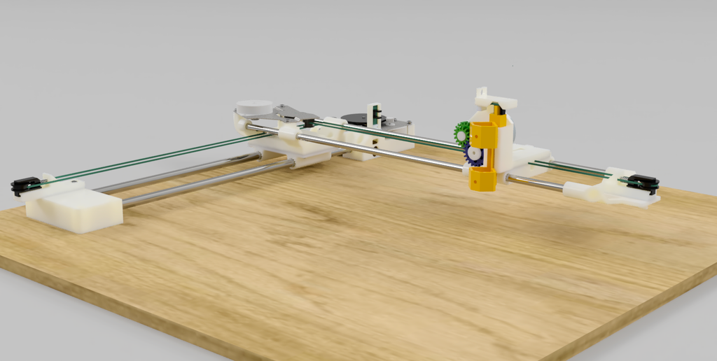
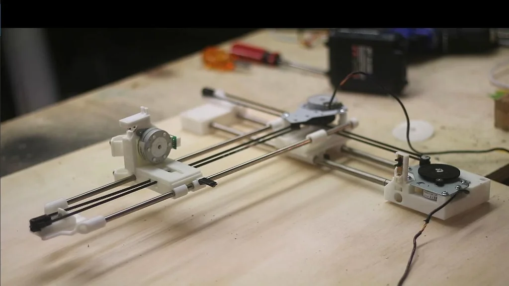
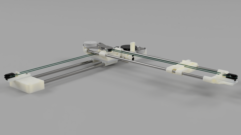
Pen Plotter from an inkjet printer-I transformed abandoned inkjet printers into a remarkable pen plotter, starting from scratch in Fusion360. By repurposing the scanner stepper motors and the document feeder motor, and incorporating sturdy steel rods into the machine, I successfully crafted a pen plotter with an impressive printing area of 230mmx230mm. You’ll love the flexibility it offers – you can design your own tools using the ‘hot shoe’ tool holder concept. The combination of these elements, along with meticulously crafted 3D printed components, culminates in the creation of a truly unique pen plotter. Supplies These are the parts required for this part of the build. Keep ALL the parts to the printer until the very end of the series. This project is only the assembly of the plotter itself. A following article with provide extra hardware required to drive the printer. These will be: Step 1: Collect Parts to Assemble X-axis To assemble the X-axis you will need. More details on parts here (YouTube link) Step 2: Insert Steel Rods Into X-axis Motor Holder Begin by assembling the x-axis motor holder and the two 8mm steel rods. Carefully insert the rods into the designated holes on the motor holder. Since the rod diameter and the holes in the motor holder are identical, the fit will be snug. This precise fit ensures a secure assembly with no room for movement. To assist with the insertion process, you can position the back of the motor holder on the corner of a table and gently tap the rods into place using a hammer. Video timestamp Step 3: Slide the X Axis Shuttle on to the X-axis Rods. Next, carefully slide the X shuttle onto the metal rods. Take note of the sensor flag, which is indicated in red. Ensure that the flag is facing towards the motor holder assembly. At the base of the motor holder, there is a sensor that is activated by this flag. Proper alignment of the flag is crucial for the sensor to function correctly Video timestamp Step 4: Assemble Tensioner Collect the x-axis tension holder and slide it onto the x-axis rods. Securely attach the x-axis tension spring and pulley holder onto the top of the tension holder using screws. Integrate the spring and tension pulley into the assembly, ensuring they are properly aligned and functioning smoothly Video timestamp Step 5: Add X Motor and Belt Position the stepper motor and gearbox on top of the X motor holder assembly. Take the belt, indicated in green, and thread it around the tension pulley, creating a loop. Then, wrap the belt around the motor belt drive gear. Securely fasten the motor into place using screws, ensuring a stable and secure attachment. Video timestamp Step 6: Install Home Sensors The x-motor holder conveniently houses both the Y and X homing sensors. Insert the Y sensor into the designated Y sensor keeper and securely screw it into place. Additionally, position the X home sensor at the base of the unit, ensuring proper alignment for optimal functionality. Video timestamp Step 7: This Completes the X-axis Assembly Congratulations you have finished the assembly of the x-axis! Make sure the shuttle moves freely along the shafts. Video timestamp Step 8: Collect Parts to Assemble X-Axis 5 More Images To assemble the Y-axis you will need. Step 9: Insert Y Rods Into Y Tension Holder Insert the 6mm rods into the tension holder. It doesn’t matter which end goes into the holder. One end has a slot for a circlip but this has no effect on the operation. Video timestamp Step 10: Y Tension Assembly Screw the tension spring holder onto the Y tension holder. Add the spring and tension pully. Video timestamp Step 11: Install Y Shuttle Install the Y shuttle on the Y rods. Take note of the homing flag (shown in red). Make sure the shuttle moves freely along the Y rods. Video timestamp Step 12: Attach Y-motor Holder Slide the Y-rods into the Y motor holder. Only partially push them in, for now, we need a gap here to put the X-axis belt in the next stage. Video timestamp Step 13: Marriage of X and Y Axis To assemble the Y-axis motor holder, attach it to the X-axis shuttle by aligning the corresponding holes. It’s important to note (as shown in the picture) that the red screw should be a short screw. Using a long screw can result in it inadvertently screwing into the X-axis steel rod, obstructing movement and potentially causing damage to the rod. Video timestamp Step 14: Install Belts Into Shuttles Thread the belt through the serrations in the Y-Axis motor holder, ensuring a snug fit. Although it may be a tight fit, carefully guide the belt through the serrations. Repeat the same process for the Y-Axis shuttle, feeding the belt through the corresponding serrations. In the images, the belt is represented by the color green to aid in visualization. Video timestamp Step 15: Install Y-Axis Belt Take one end of the belt and wrap it around the y-axis pulley. Then, guide the other end around the motor drive pulley and ensure it is properly aligned. Proceed to screw the motor into place securely. It’s important to note that the motor assembly is upside down compared to the x-axis configuration. Video timestamp Step 16: Both Axis Complete! This concludes the construction of the X and Y axis! Turn the motor on each axis to make sure the move each shuttle freely. Step 17: Assemble Tool Head You have the flexibility to create your own tool head for the pen plotter, and it’s straightforward to attach your custom design to the Y-axis shuttle. In my design, I utilized the stepper motor from the printer’s document handler. This choice was made to ensure that all the parts used (excluding the 3D printed components) are sourced from the provided printers. It’s worth noting that while it is common to use servos to activate the pen, they tend to burn out over time. By using a stepper motor, I aimed to achieve a more reliable mechanism. To simplify the explanation, I have color-coded the gears in the picture. When attaching the motor, make sure to screw it in with the plug pointing in the direction depicted in the picture. The screws should be inserted from the front side, and you should have a few machine screws with captured washers at your disposal. To finish off slide one more sensor across the top of the tool. This is for Z-axis homing. Video timestamp Step 18: Attach to a Base Board Now that the machine is fully assembled, the next step is to securely attach it to a flat and sturdy piece of wood. Place the unit on the wood and carefully mark out the hole positions provided on the X-axis motor holder and tensioner holder. Use a drill with a 2mm bit to create holes in each of the marked-out locations. Finally, fasten the pen plotter onto the designated location by screwing it firmly into place. Video timestamp Step 19: Conclusion Congratulations on completing the assembly! If you are already familiar with GRBL, configuring the software side of things should be relatively straightforward for you. However, if you are new to it, you’re in luck because I can guide you through the process in my next tutorial on installing and configuring GRBL you can find this here.
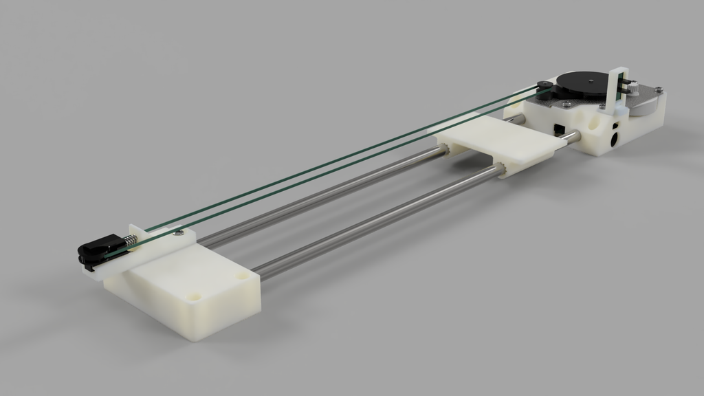
I transformed abandoned inkjet printers into a remarkable pen plotter, starting from scratch in Fusion360. By repurposing the scanner stepper motors and the document feeder motor, and incorporating sturdy steel rods into the machine, I successfully crafted a pen plotter with an impressive printing area of 230mmx230mm. You’ll love the flexibility it offers – you can design your own tools using the ‘hot shoe’ tool holder concept. The combination of these elements, along with meticulously crafted 3D printed components, culminates in the creation of a truly unique pen plotter.
Supplies
These are the parts required for this part of the build. Keep ALL the parts to the printer until the very end of the series.
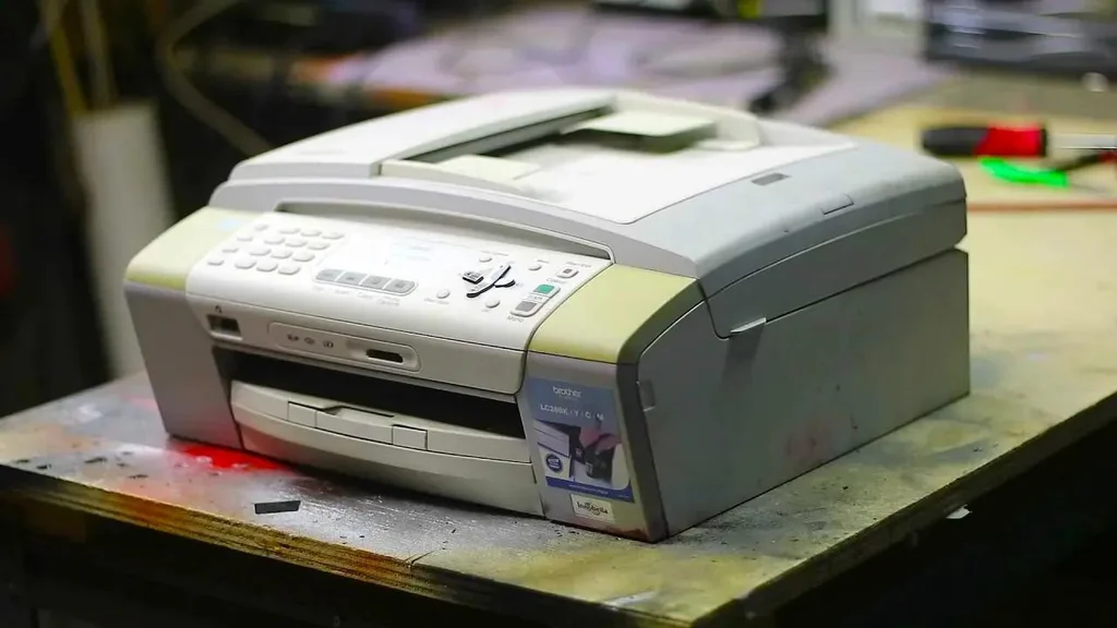
2 x MFC-290C. This is the printer I used but I see even modern Brother printers use the same scanner assembly.
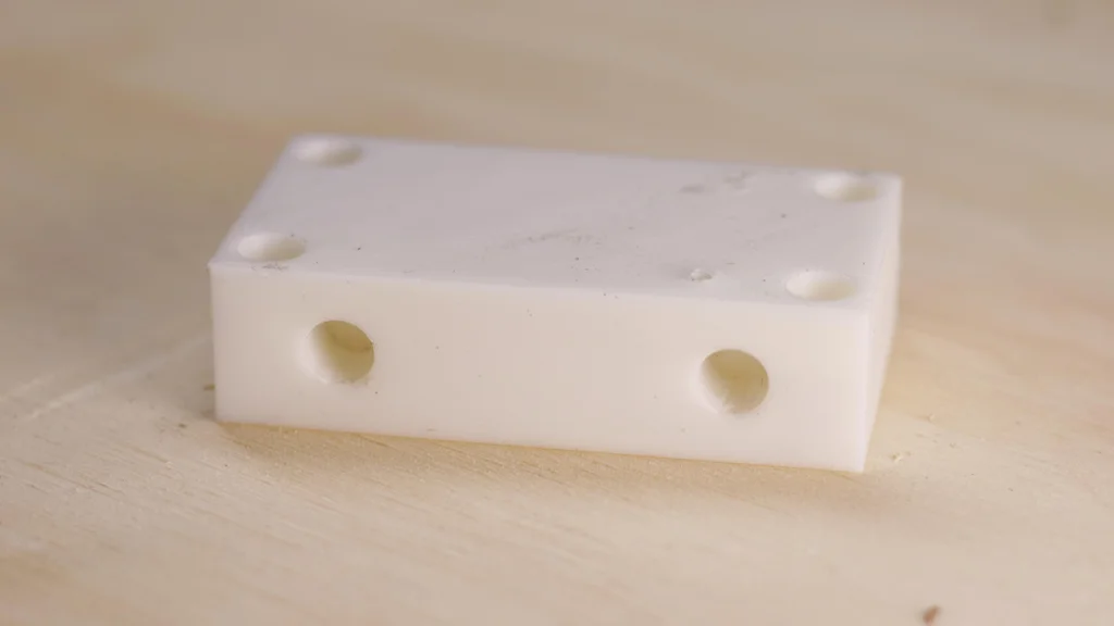
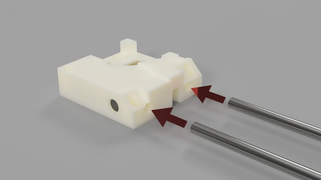
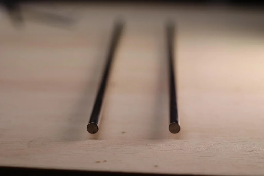
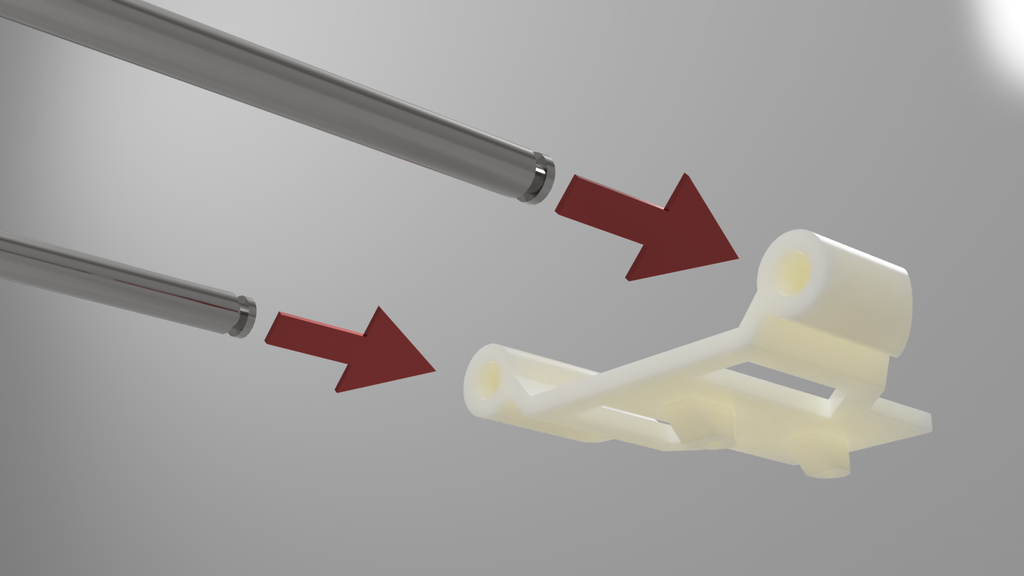
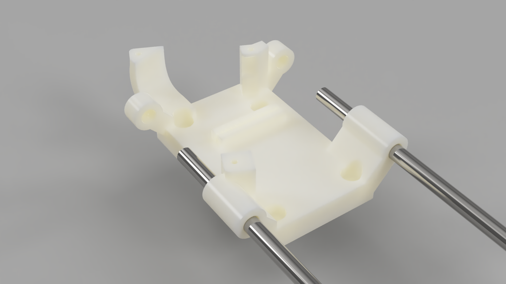
Step 2: Insert Steel Rods Into X-axis Motor Holder
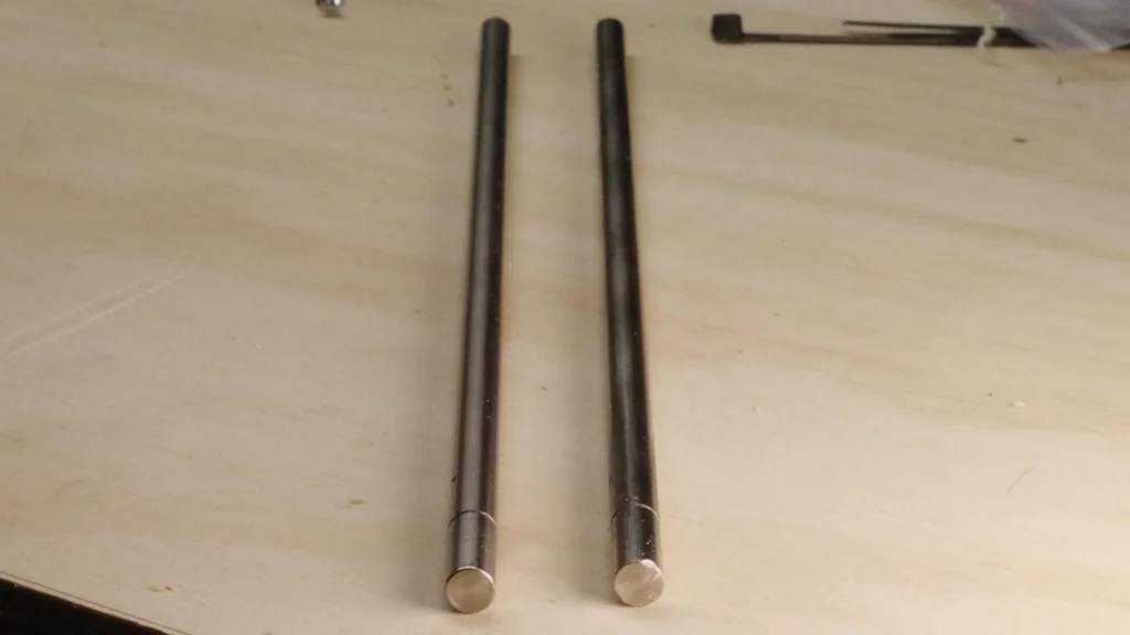
Begin by assembling the x-axis motor holder and the two 8mm steel rods. Carefully insert the rods into the designated holes on the motor holder. Since the rod diameter and the holes in the motor holder are identical, the fit will be snug. This precise fit ensures a secure assembly with no room for movement. To assist with the insertion process, you can position the back of the motor holder on the corner of a table and gently tap the rods into place using a hammer.
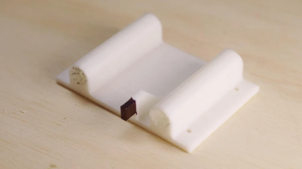
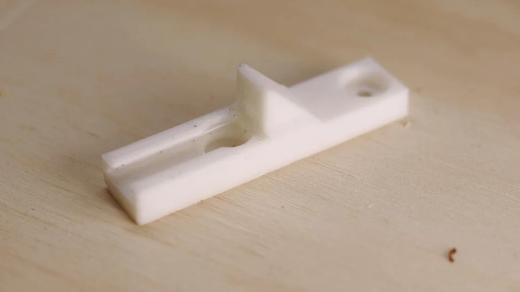
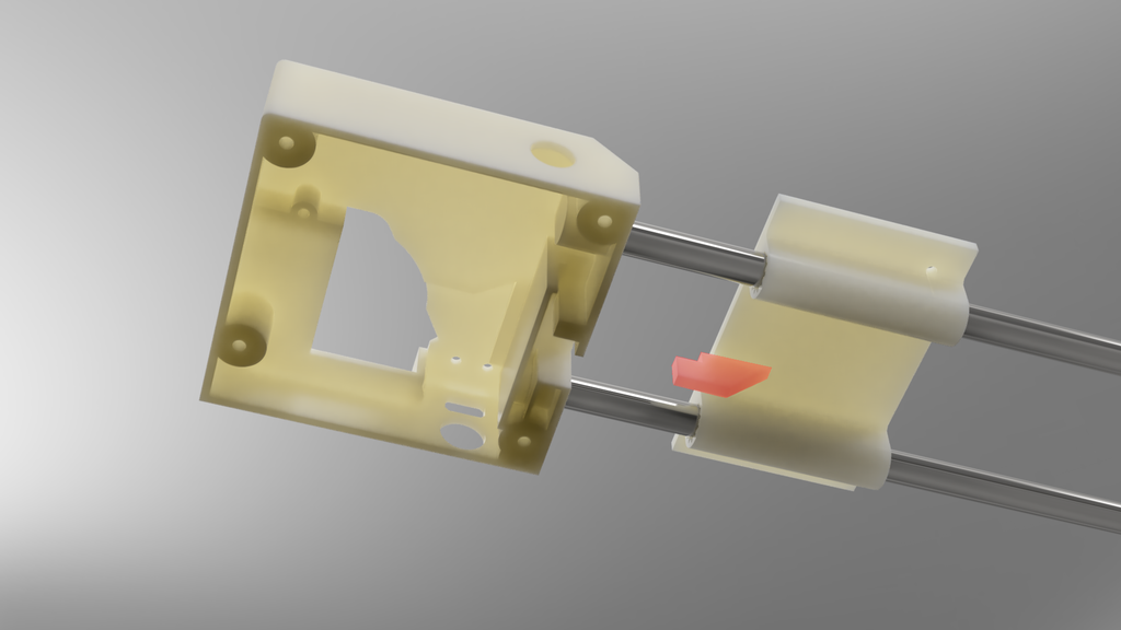
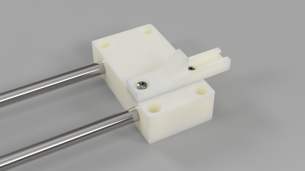
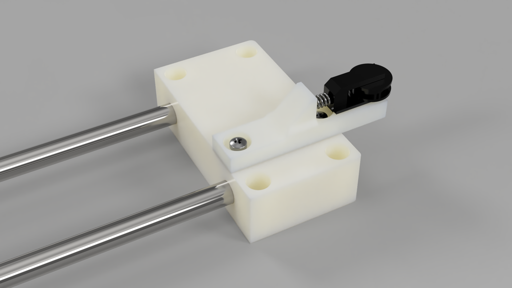
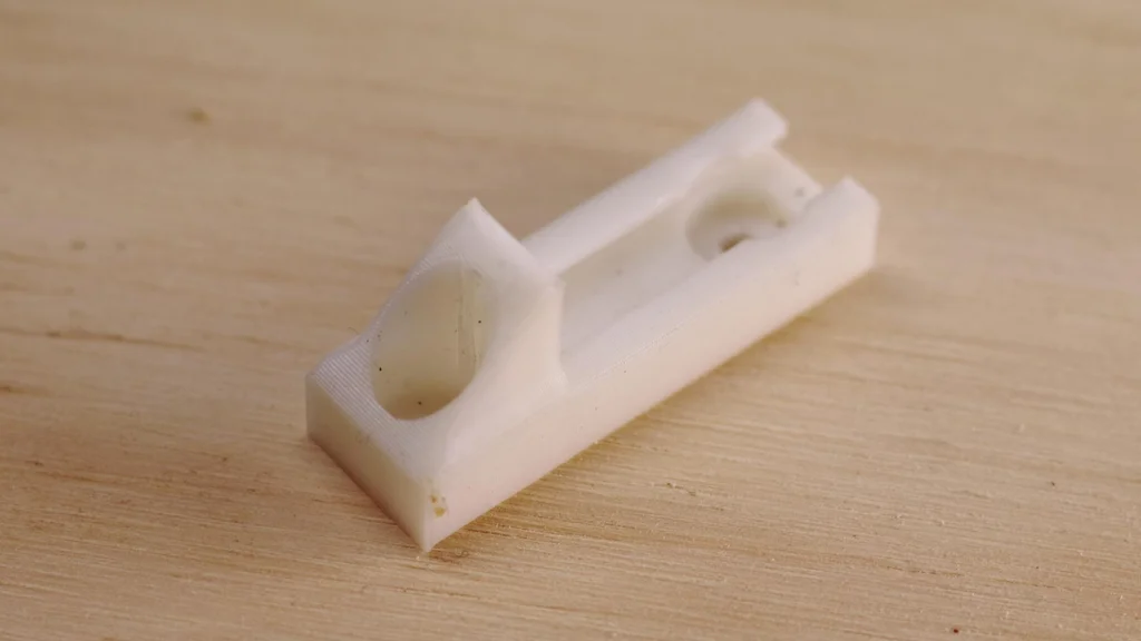
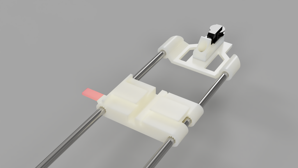
Step 3: Slide the X Axis Shuttle on to the X-axis Rods.
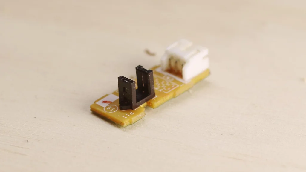
Next, carefully slide the X shuttle onto the metal rods. Take note of the sensor flag, which is indicated in red. Ensure that the flag is facing towards the motor holder assembly. At the base of the motor holder, there is a sensor that is activated by this flag. Proper alignment of the flag is crucial for the sensor to function correctly
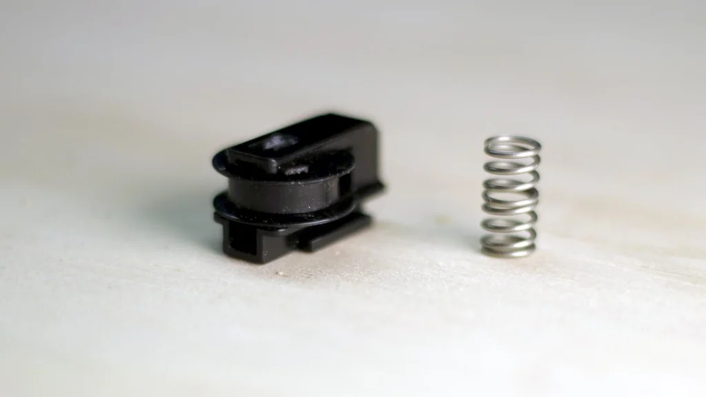
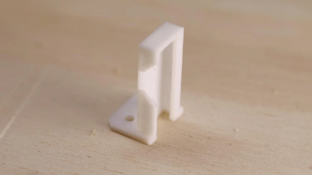
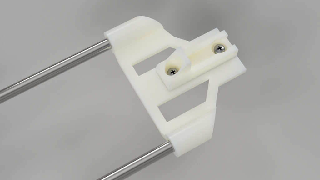
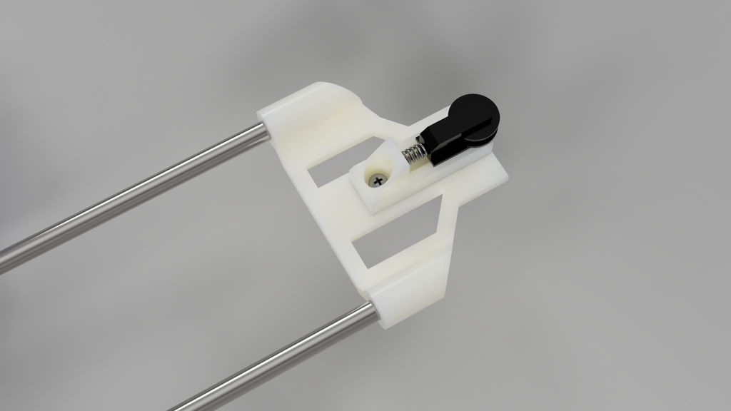
Collect the x-axis tension holder and slide it onto the x-axis rods. Securely attach the x-axis tension spring and pulley holder onto the top of the tension holder using screws. Integrate the spring and tension pulley into the assembly, ensuring they are properly aligned and functioning smoothly
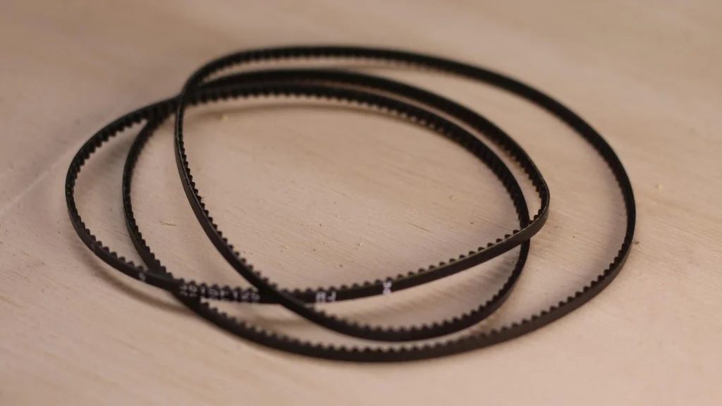
Position the stepper motor and gearbox on top of the X motor holder assembly. Take the belt, indicated in green, and thread it around the tension pulley, creating a loop. Then, wrap the belt around the motor belt drive gear. Securely fasten the motor into place using screws, ensuring a stable and secure attachment.
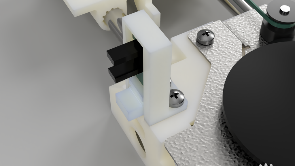
The x-motor holder conveniently houses both the Y and X homing sensors. Insert the Y sensor into the designated Y sensor keeper and securely screw it into place. Additionally, position the X home sensor at the base of the unit, ensuring proper alignment for optimal functionality.
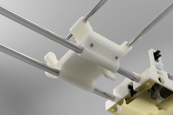
Insert the 6mm rods into the tension holder. It doesn’t matter which end goes into the holder. One end has a slot for a circlip but this has no effect on the operation.
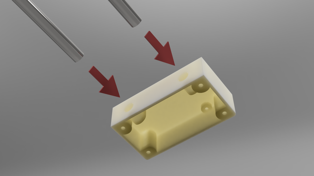
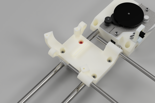
To assemble the Y-axis motor holder, attach it to the X-axis shuttle by aligning the corresponding holes. It’s important to note (as shown in the picture) that the red screw should be a short screw. Using a long screw can result in it inadvertently screwing into the X-axis steel rod, obstructing movement and potentially causing damage to the rod.
Video timestamp
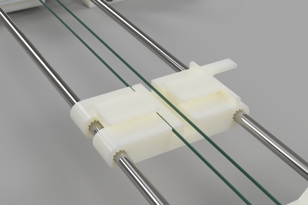
Step 14: Install Belts Into Shuttles
Thread the belt through the serrations in the Y-Axis motor holder, ensuring a snug fit. Although it may be a tight fit, carefully guide the belt through the serrations. Repeat the same process for the Y-Axis shuttle, feeding the belt through the corresponding serrations. In the images, the belt is represented by the color green to aid in visualization.
Take one end of the belt and wrap it around the y-axis pulley. Then, guide the other end around the motor drive pulley and ensure it is properly aligned. Proceed to screw the motor into place securely. It’s important to note that the motor assembly is upside down compared to the x-axis configuration.
This concludes the construction of the X and Y axis! Turn the motor on each axis to make sure the move each shuttle freely.
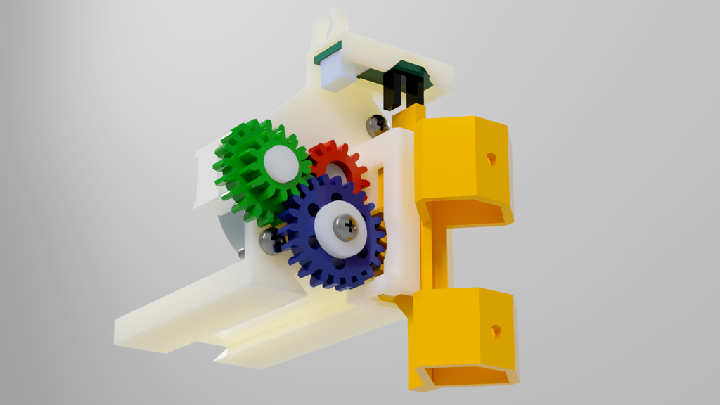
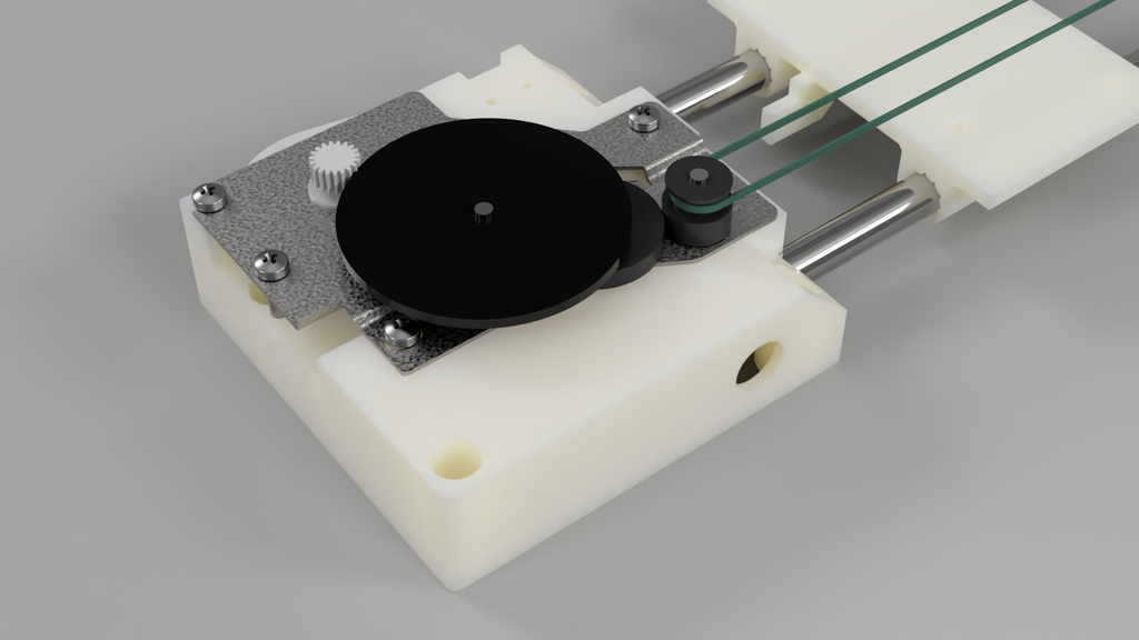
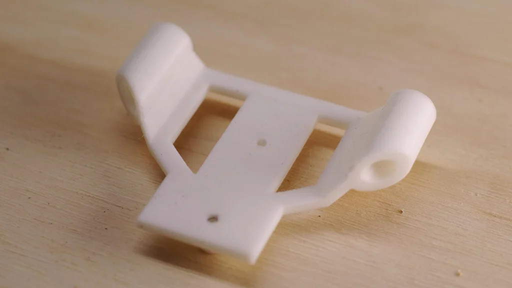
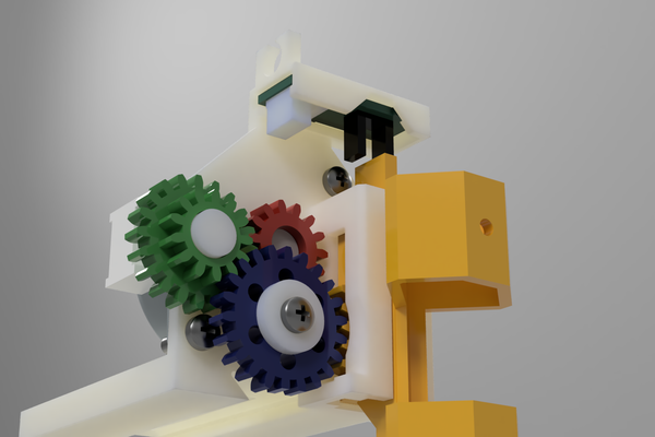
Step 17: Assemble Tool Head
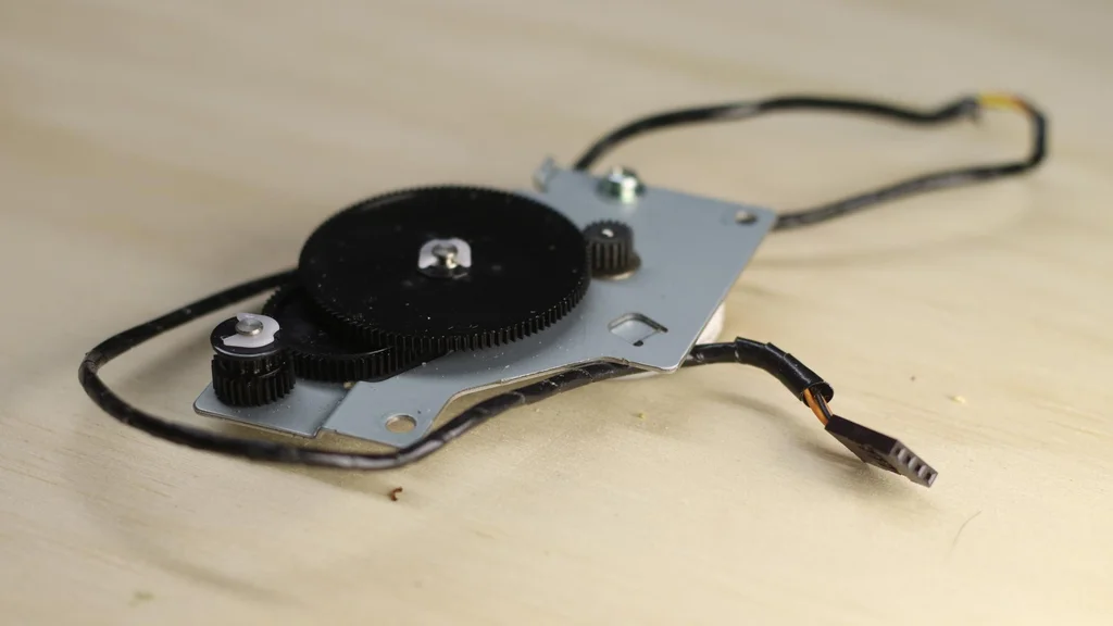
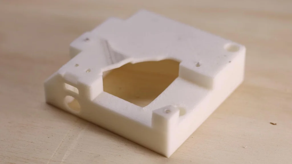
You have the flexibility to create your own tool head for the pen plotter, and it’s straightforward to attach your custom design to the Y-axis shuttle. In my design, I utilized the stepper motor from the printer’s document handler. This choice was made to ensure that all the parts used (excluding the 3D printed components) are sourced from the provided printers.
It’s worth noting that while it is common to use servos to activate the pen, they tend to burn out over time. By using a stepper motor, I aimed to achieve a more reliable mechanism. To simplify the explanation, I have color-coded the gears in the picture.
When attaching the motor, make sure to screw it in with the plug pointing in the direction depicted in the picture. The screws should be inserted from the front side, and you should have a few machine screws with captured washers at your disposal.
Red gear. This is the gear attached to the stepper motor. The diameter of the motor gear is bigger than the hole in the gear itself. Heat up the gear with a heat gun or similar then push the plastic gear into the stepper gear. This will create a tight fit.
Push the green gear on with the larger gear to the back.
Push on the blue gear, and the washer and finally screw this in place.
The yellow pen holder feeds in from the bottom.
To finish off slide one more sensor across the top of the tool. This is for Z-axis homing.
Now that the machine is fully assembled, the next step is to securely attach it to a flat and sturdy piece of wood. Place the unit on the wood and carefully mark out the hole positions provided on the X-axis motor holder and tensioner holder. Use a drill with a 2mm bit to create holes in each of the marked-out locations.
Finally, fasten the pen plotter onto the designated location by screwing it firmly into place.
Congratulations on completing the assembly! If you are already familiar with GRBL, configuring the software side of things should be relatively straightforward for you. However, if you are new to it, you’re in luck because I can guide you through the process in my next tutorial on installing and configuring GRBL you can find this here.
Making your own circuit board with the toner transfer process – 5 Methods tested.-The toner transfer process is a common method used to create printed circuit boards (PCBs) in a DIY setting or small-scale production. The process involves transferring a printed image of a circuit design onto a copper-clad board, which is then etched to remove the unneeded copper and leave the desired circuit pattern. The process of transferring toner onto a circuit board remains the same, but the methods of achieving it can differ. I conducted a brief search on YouTube and tried the top four methods, as well as creating my own approach. I utilized the test pattern from here, which posed a challenge for the toner transfer process due to its intricate design with numerous thin lines and small pads. In this experiment, I focused solely on the toner transfer and not the etching process. In general, a successful toner transfer usually ensures that the image will etch successfully as well. It is essential to have an iron for this process. Additionally, the copper-clad board must be immaculately clean, free from any residue, including fingerprints. The cleanliness of the board is crucial for the success of the transfer, as any impurities can affect the outcome. The process can only be completed with a toner based printer such as a laser printer. Inkjet printers can not be used. The Methods. 1. The OG toner transfer. Required tools This is the toner transfer process in its simplest form: 2. Vinyl backing paper. Required tools Check the original video here: This toner transfer process uses vinyl wrap as the backing material. The vinyl wrap has a shiny side and a matte side with markings, and cannot be directly fed into the printer due to its tendency to curl and become flimsy. To resolve this issue, the vinyl wrap can be taped onto a regular piece of paper and then fed through the printer. After printing, remove the vinyl wrap from the paper and place it onto the copper-clad board. Apply heat and pressure to the paper for several minutes, causing the toner to adhere to the copper. The backing paper from the vinyl wrap should then easily peel away.” 3. Acetone cocktail. Required tools Check the original video here: By diluting acetone with isopropyl alcohol, the effectiveness of the acetone is reduced, making the toner somewhat sticky and more able to adhere to the copper-clad board. Do not use acetone that contains any impurities like moisturizer. Most chemist or supermarket purchased acetone contains chemicals other than acetone. To use this process, clean both the print on the glossy paper and the copper-clad board with isopropyl alcohol. Then, coat the board with the acetone and isopropyl alcohol mixture. Place the print onto the board and after 10 seconds apply pressure on the print. Finally, immerse the board in water, and the paper should peel off, revealing the toner that has adhered to the board 4. Spray paint Required tools Check the orignal video here: The first step in this process is to apply paint containing acetone onto a copper-clad board. After the board is painted, place a print on vinal backing paper onto it, and gently rub the tracks so that the toner adheres to the paint. Next, soak the board in water to separate the paper from the board. The next step is to remove the paint that covers the areas without toner, which is where we want to etch. To do this, gently dab the paint with a small amount of isopropyl alcohol using a rag, without rubbing. Avoid using excessive amounts of IPA as it may dissolve the paint layer and disrupt the toner. If you are succsesfull the toner will be left behind while the paint has been removed. 5. Transparency film Required tools In this procedure, transparency film is utilized to transfer the toner. First, print your design onto the transparency film. Then, use an iron to apply pressure onto the transparency and the board for a few minutes. Place the board in the fridge to cool. This seems to ensure a better transfer. Carefully peel the film off the board. Conclusion For me the transparecy method had the best result. With a bit of practice all the other methods may work just as well. Check the table below for my notes on each. Method Heat Water Pressure Notes Toner transfer ✔️ ✔️ ✔️ The original verson, generally works pretty well when executed correctly. Vinyl backing paper ✔️ ✔️ ✔️ Great transfer, make sure your vinyl is not damaged as this will effect the transfer. Acetone cocktail ❌ ✔️ ✔️ I couldn’t really get this to work effectivly. Spray paint ❌ ✔️ ❌ Great transfer but removing the paint was tricky. Would work well with thick lines. Transparency ✔️ ❌ ✔️ Overall the best method so far.
The toner transfer process is a common method used to create printed circuit boards (PCBs) in a DIY setting or small-scale production. The process involves transferring a printed image of a circuit design onto a copper-clad board, which is then etched to remove the unneeded copper and leave the desired circuit pattern.
The process of transferring toner onto a circuit board remains the same, but the methods of achieving it can differ. I conducted a brief search on YouTube and tried the top four methods, as well as creating my own approach.
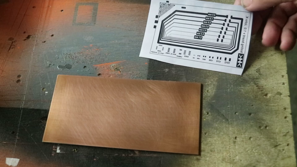
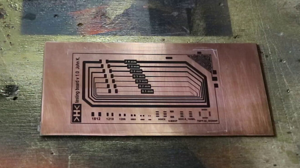
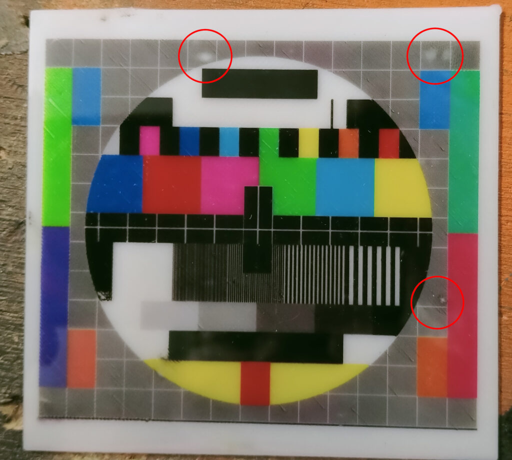
I utilized the test pattern from here, which posed a challenge for the toner transfer process due to its intricate design with numerous thin lines and small pads. In this experiment, I focused solely on the toner transfer and not the etching process. In general, a successful toner transfer usually ensures that the image will etch successfully as well.
It is essential to have an iron for this process. Additionally, the copper-clad board must be immaculately clean, free from any residue, including fingerprints. The cleanliness of the board is crucial for the success of the transfer, as any impurities can affect the outcome.
The process can only be completed with a toner based printer such as a laser printer. Inkjet printers can not be used.
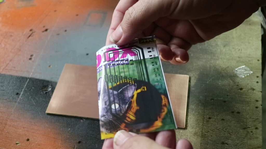
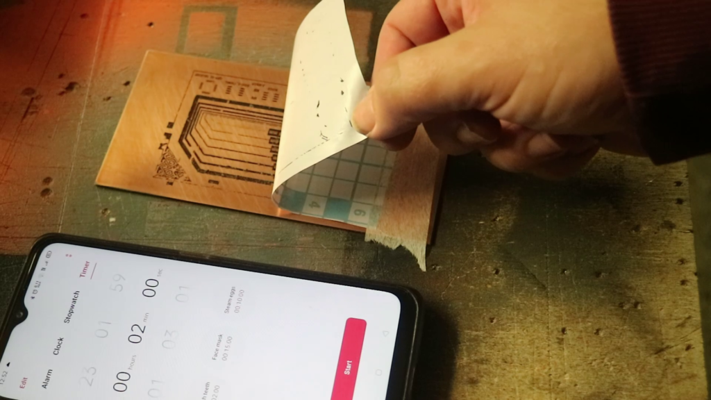
This toner transfer process uses vinyl wrap as the backing material. The vinyl wrap has a shiny side and a matte side with markings, and cannot be directly fed into the printer due to its tendency to curl and become flimsy. To resolve this issue, the vinyl wrap can be taped onto a regular piece of paper and then fed through the printer.
Slowly remove the vinyl backing paper
After printing, remove the vinyl wrap from the paper and place it onto the copper-clad board. Apply heat and pressure to the paper for several minutes, causing the toner to adhere to the copper. The backing paper from the vinyl wrap should then easily peel away.”
By diluting acetone with isopropyl alcohol, the effectiveness of the acetone is reduced, making the toner somewhat sticky and more able to adhere to the copper-clad board.
Do not use acetone that contains any impurities like moisturizer. Most chemist or supermarket purchased acetone contains chemicals other than acetone.
To use this process, clean both the print on the glossy paper and the copper-clad board with isopropyl alcohol. Then, coat the board with the acetone and isopropyl alcohol mixture. Place the print onto the board and after 10 seconds apply pressure on the print. Finally, immerse the board in water, and the paper should peel off, revealing the toner that has adhered to the board
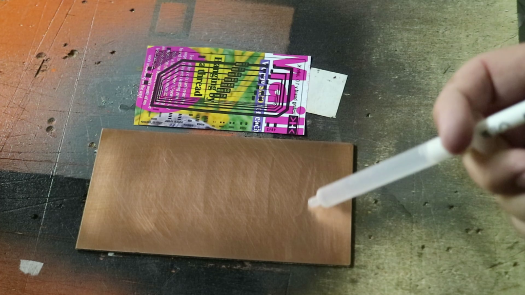
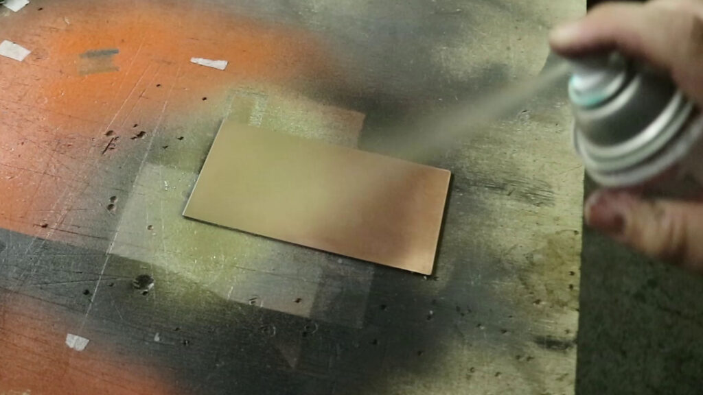
The first step in this process is to apply paint containing acetone onto a copper-clad board. After the board is painted, place a print on vinal backing paper onto it, and gently rub the tracks so that the toner adheres to the paint. Next, soak the board in water to separate the paper from the board.
This process provides a good transfer
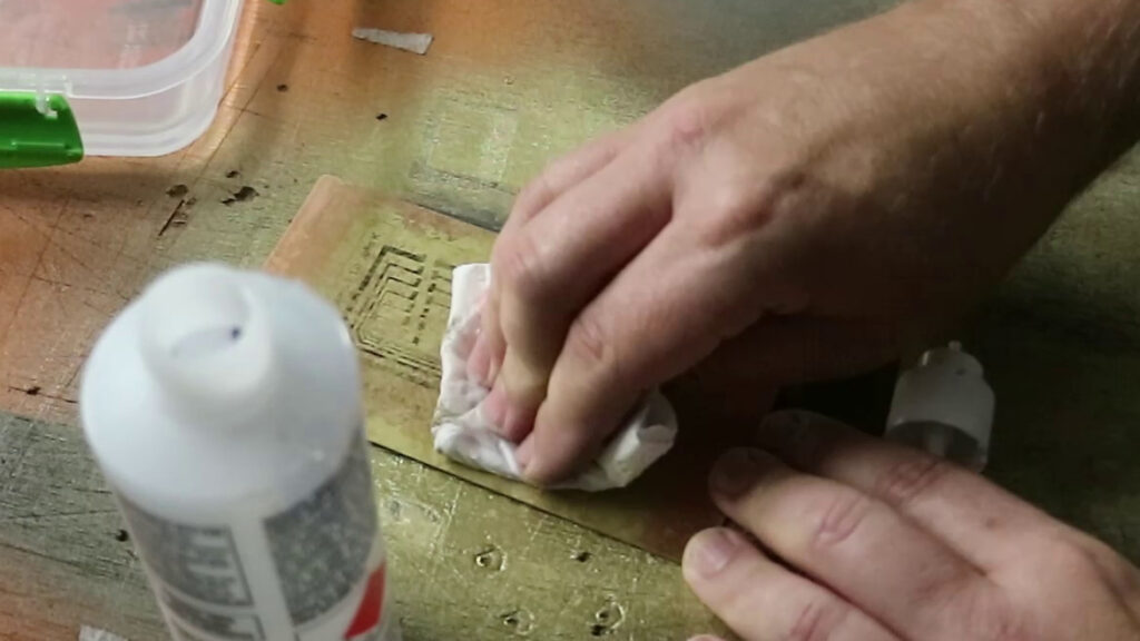
The next step is to remove the paint that covers the areas without toner, which is where we want to etch. To do this, gently dab the paint with a small amount of isopropyl alcohol using a rag, without rubbing. Avoid using excessive amounts of IPA as it may dissolve the paint layer and disrupt the toner.
Dab the board with a cloth and IPA
If you are succsesfull the toner will be left behind while the paint has been removed.
5. Transparency film
Required tools
Transparency film
Iron
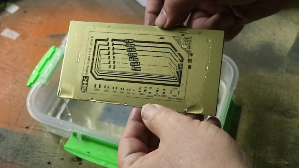
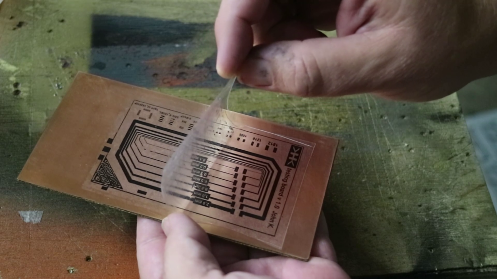
In this procedure, transparency film is utilized to transfer the toner. First, print your design onto the transparency film. Then, use an iron to apply pressure onto the transparency and the board for a few minutes.
Transparency allows for easy alignment
Place the board in the fridge to cool. This seems to ensure a better transfer.
Carefully peel the film off the board.
Remove the film slowly after cooling
Conclusion
For me the transparecy method had the best result. With a bit of practice all the other methods may work just as well. Check the table below for my notes on each.
Method
Heat
Water
Pressure
Notes
Toner transfer
✔️
✔️
✔️
The original verson, generally works pretty well when executed correctly.
Vinyl backing paper
✔️
✔️
✔️
Great transfer, make sure your vinyl is not damaged as this will effect the transfer.
Acetone cocktail
❌
✔️
✔️
I couldn’t really get this to work effectivly.
Spray paint
❌
✔️
❌
Great transfer but removing the paint was tricky. Would work well with thick lines.
Transparency
✔️
❌
✔️
Overall the best method so far.
Tips for toner transfer with 3D printing-It is possible to transfer toner onto your 3D prints. Check the original guide on this process found here: https://www.reddit.com/r/FDM_TonerTransfer/ Here a few tips I have found in my own testing. The beauty of this process is you can alter the properties of the first layer as much as you like and it will not effect the rest of the job. Z-Offset Z-Offset lets you alter the nozzle height from your leveled bed. Being higher or lower may improve your result. By examining the image from left to right, the impact of Z-offset becomes evident. On the far left, the Z-offset is set too low and causes toner to be scraped off the transparency. However, as we progress to the right and incrementally raise the Z-offset by 0.1mm, the white vertical lines become more distinct and the image appears lighter. For my prints I was using .1mm but this really depends on your bed leveling. Temperature You will want to run the initial layer hotter than you normally would. I usually print at around 210c on the hotend and 50c on the bed. For a good result I had to move these to 220c for the hotend and 60c for the bed. Layer height This is slightly self explanatory. This is the layer height which I set to .1 for the first layer. Initial layer line width factor This is the gap between the lines on your inital layer a heigher % will increase the gap between these lines. Reducing this value increases the lines on the inital layers and have a “finer” print. I found setting this to 60% gave me a good result. Removing the transparency from the print. I found the best method is to wait for 30 mins or so after the print is completed before trying to remove the transparency from the object. Pulling it off too early I have found some toner adheres to the sheet rather than the print. If you are careful you can remove the print attached to the sheet anytime allowing you to start a new job. Placing the sheet on the bed prior to printing. Make sure there is no dust on the bed or the bed side of the transparency. The smallest particle will leave imperfections in the transfer. In my video I demonstrated not removing the outline, this is wrong. Once you tape down your transparency on one side remove anything that is on the bed.
It is possible to transfer toner onto your 3D prints. Check the original guide on this process found here: https://www.reddit.com/r/FDM_TonerTransfer/
Here a few tips I have found in my own testing.
The beauty of this process is you can alter the properties of the first layer as much as you like and it will not effect the rest of the job.
Z-Offset
Z-Offset lets you alter the nozzle height from your leveled bed. Being higher or lower may improve your result.
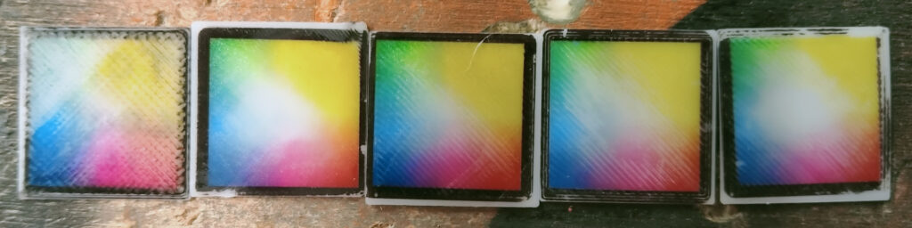
Different levels of Z offset
By examining the image from left to right, the impact of Z-offset becomes evident. On the far left, the Z-offset is set too low and causes toner to be scraped off the transparency. However, as we progress to the right and incrementally raise the Z-offset by 0.1mm, the white vertical lines become more distinct and the image appears lighter.
For my prints I was using .1mm but this really depends on your bed leveling.
Temperature
You will want to run the initial layer hotter than you normally would. I usually print at around 210c on the hotend and 50c on the bed. For a good result I had to move these to 220c for the hotend and 60c for the bed.
Layer height
This is slightly self explanatory. This is the layer height which I set to .1 for the first layer.
Initial layer line width factor
This is the gap between the lines on your inital layer a heigher % will increase the gap between these lines. Reducing this value increases the lines on the inital layers and have a “finer” print. I found setting this to 60% gave me a good result.
Removing the transparency from the print.
I found the best method is to wait for 30 mins or so after the print is completed before trying to remove the transparency from the object. Pulling it off too early I have found some toner adheres to the sheet rather than the print. If you are careful you can remove the print attached to the sheet anytime allowing you to start a new job.
Placing the sheet on the bed prior to printing.
Make sure there is no dust on the bed or the bed side of the transparency. The smallest particle will leave imperfections in the transfer.
Spots
In my video I demonstrated not removing the outline, this is wrong. Once you tape down your transparency on one side remove anything that is on the bed.


 Unlock with Patreon