Getting a old printer motor to work
With over two decades of expertise troubleshooting printers and copiers, I’ve encountered countless machines loaded with motors. The intricacies of how these motors functioned were often straightforward: either they worked, or they didn’t. In cases where they didn’t, the solution was often to discard the malfunctioning unit; if they did, the issue lay elsewhere.
Throughout this extensive period, I’ve encountered and worked with hundreds of outrunner motors. Distinguished by the unique characteristic of the motor body spinning, not just the shaft, these motors offer a unique combination of low speed and high torque. Their strength lies in their ability to efficiently maneuver challenging components such as developer tanks or drums within printers.
For my latest venture, the Facehugger project, I’ve salvaged one of these outrunner motors from an HP color printer. Beyond being low-profile, it boasts ample power to bring my facehuggers to life through animation.
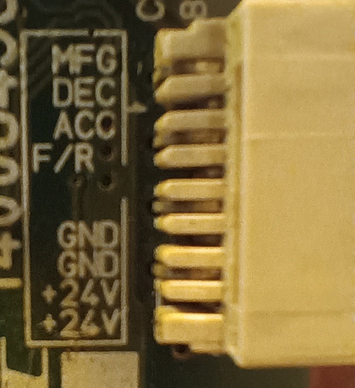
However, one hurdle stands in the way: the peculiar pinout configuration of the motor. While the markings +24 and GND align logically, the subsequent labels—F/R (presumably for forward and reverse), ACC, DEC, and MFG—present a puzzle. Deciphering their functions isn’t straightforward. If you’ve stumbled upon this blog through a Google search, I hope you find the answers you seek. Personally, my breakthrough came from a stroke of luck during an eBay auction, as these details proved elusive elsewhere in my quest.
- F/R is indeed forward and reverse.
- ACC needs to go low, this is possibly “active”. When this goes low the motor can drive.
- DEC is the pin for your PWM (pulse width modulation) or how fast you want your motor to spin.
- MFG is motor frame ground from what I understand.
In my test, I simply tied ACC and F/R to ground then applied PWM to the DEC using an UNO and the code below.
#include <TimerOne.h>

const int ledPin = 9;  // PWM capable pin for LED

void setup() {
  pinMode(ledPin, OUTPUT);

  // Set the desired PWM frequency (in Hz)
  Timer1.initialize(1000);  // 1 kHz
  Timer1.pwm(9, 512);  // 50% duty cycle, you can adjust as needed
}

void loop() {
  // Your main code here
}
This code uses a potentiometer to alter the PWM signal to increase and decrease the speed of the motor. MFG is not connected. If your project has a metal frame I would assume you connect this to your metal frame to reduce noise.