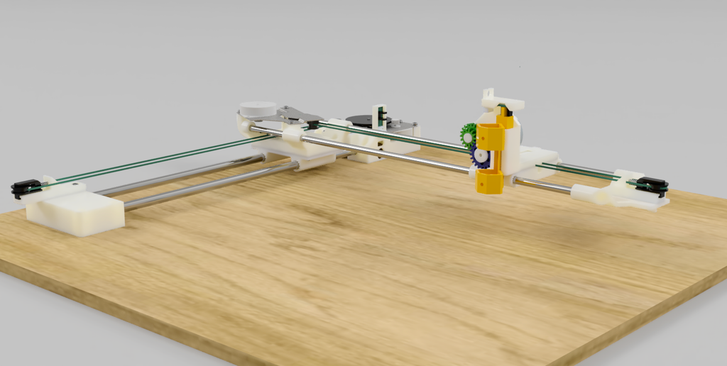
Pen Plotter from an inkjet printer

I transformed abandoned inkjet printers into a remarkable pen plotter, starting from scratch in Fusion360. By repurposing the scanner stepper motors and the document feeder motor, and incorporating sturdy steel rods into the machine, I successfully crafted a pen plotter with an impressive printing area of 230mmx230mm. You’ll love the flexibility it offers – you can design your own tools using the ‘hot shoe’ tool holder concept. The combination of these elements, along with meticulously crafted 3D printed components, culminates in the creation of a truly unique pen plotter.
Supplies
These are the parts required for this part of the build. Keep ALL the parts to the printer until the very end of the series.
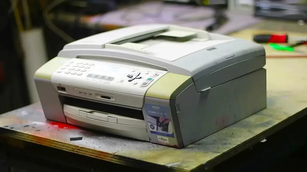
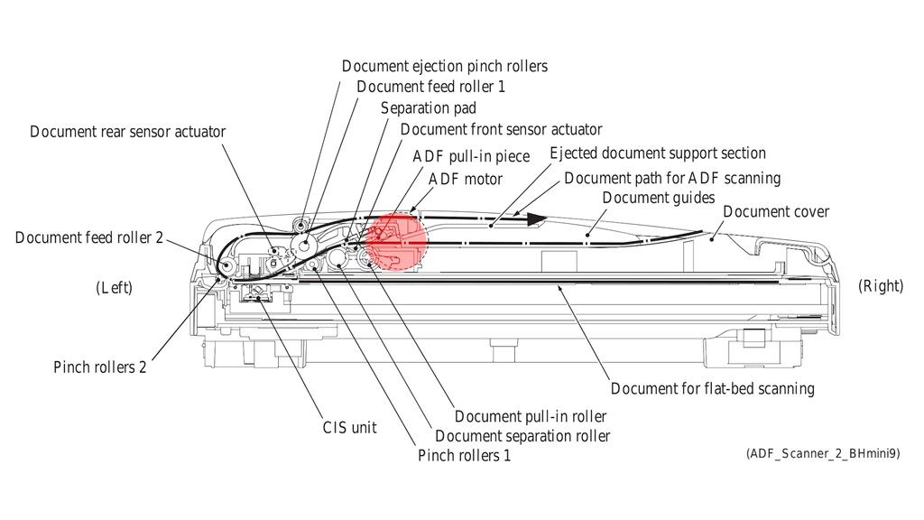
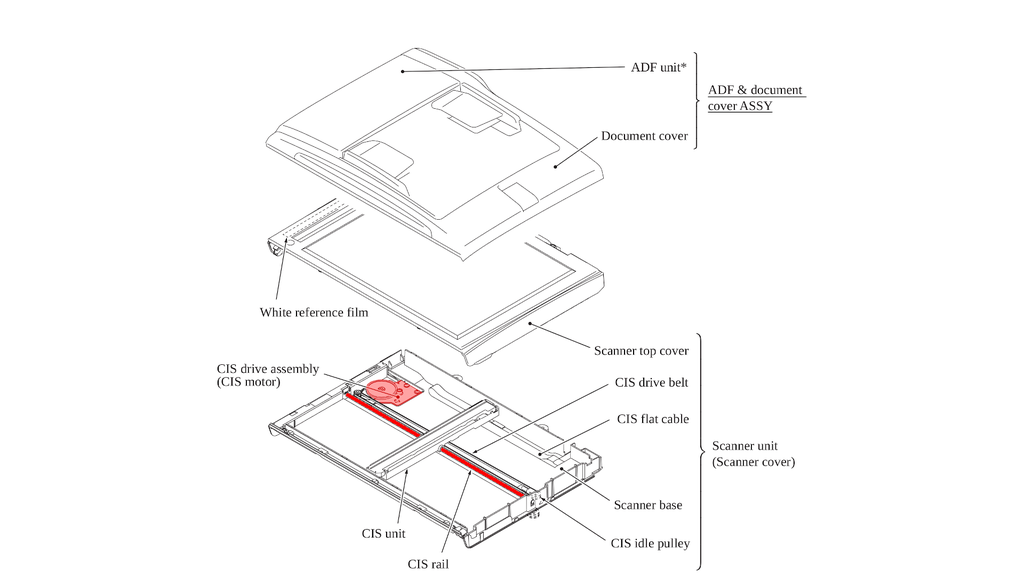
- 2 x MFC-290C. This is the printer I used but I see even modern Brother printers use the same scanner assembly.
- 3D printed parts using the STLs provided.
- A solid piece of flat wood approx 500x500mm
This project is only the assembly of the plotter itself. A following article with provide extra hardware required to drive the printer. These will be:
- Arduino UNO
- Arduino CNC shield
- Laptop power supply
Step 1: Collect Parts to Assemble X-axis
To assemble the X-axis you will need.
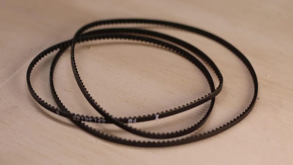
- Toothed belt
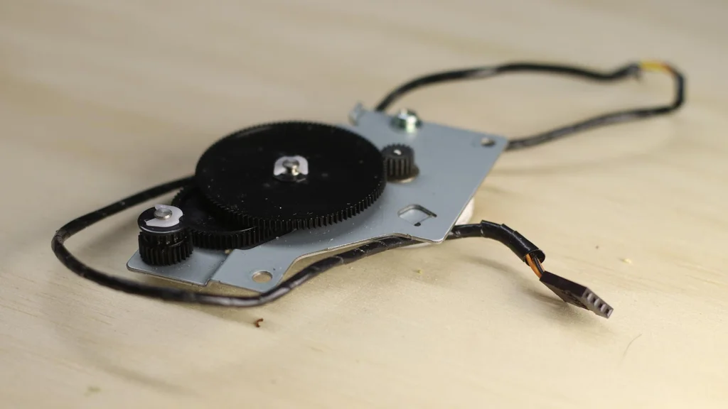
- Stepper motor and bracket
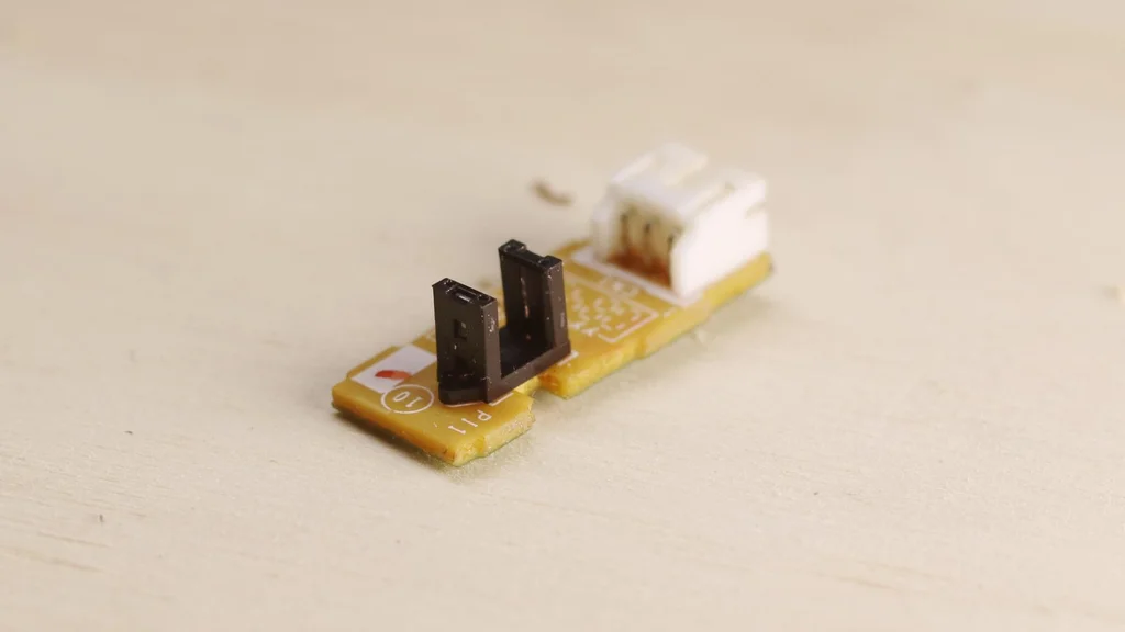
- 2 x sensors
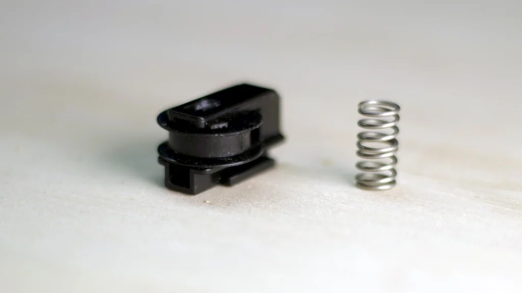
- 1 tension roller and spring
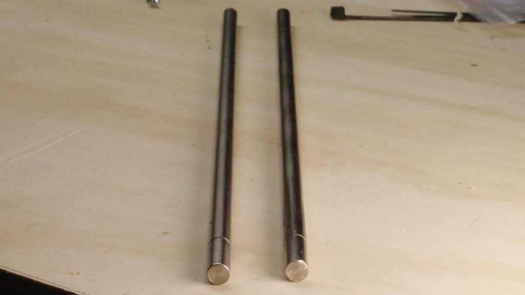
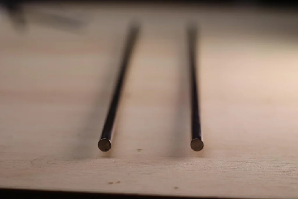
- 2 x 8mm steel rods
- x-axis shuttle
- x-axis tension holder
- x-axis tension roller holder
- y-axis home sensor keeper
- x-axis motor holder
More details on parts here (YouTube link)
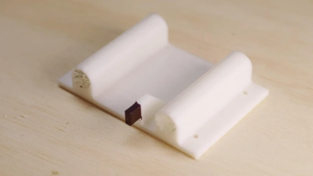
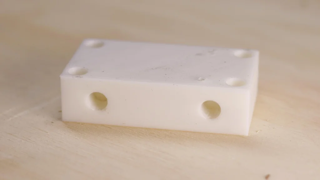
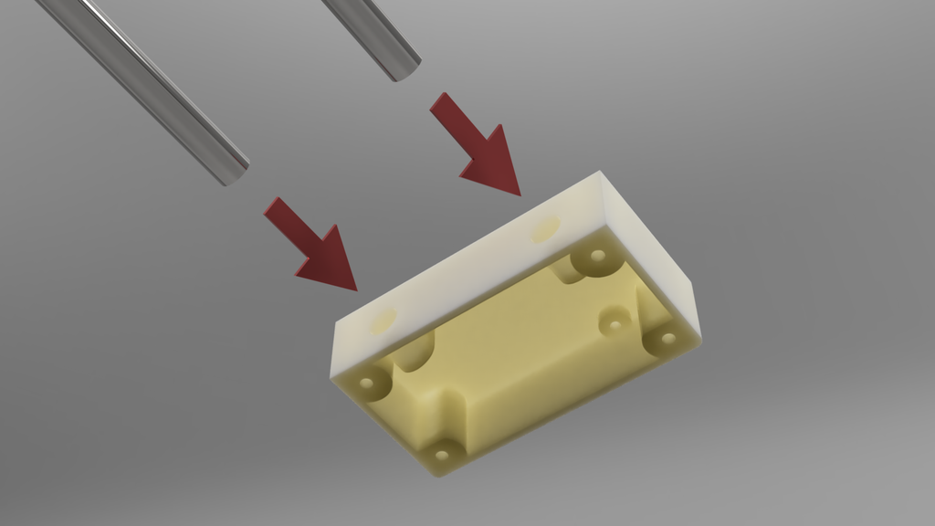
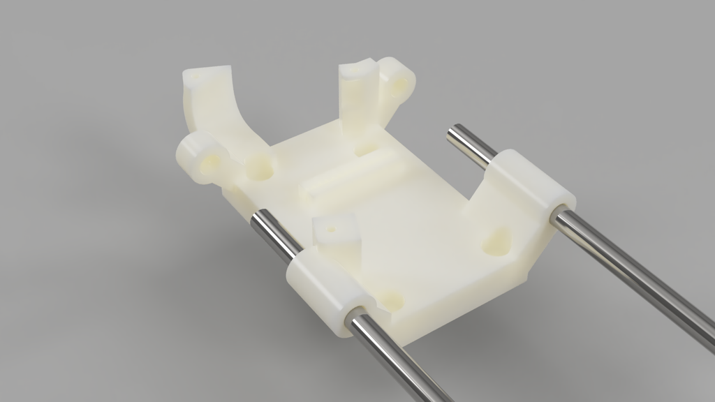
Step 2: Insert Steel Rods Into X-axis Motor Holder
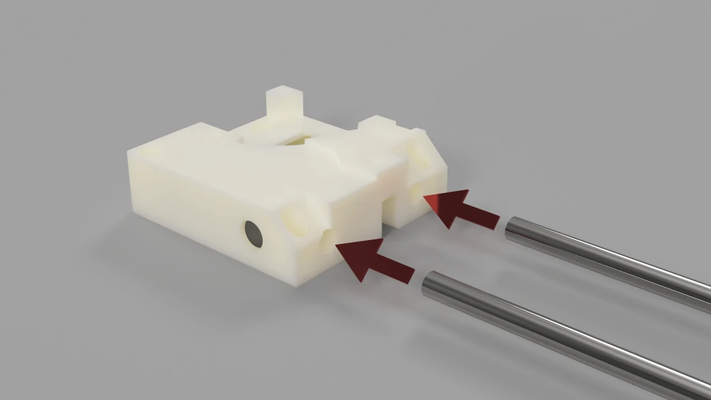
Begin by assembling the x-axis motor holder and the two 8mm steel rods. Carefully insert the rods into the designated holes on the motor holder. Since the rod diameter and the holes in the motor holder are identical, the fit will be snug. This precise fit ensures a secure assembly with no room for movement. To assist with the insertion process, you can position the back of the motor holder on the corner of a table and gently tap the rods into place using a hammer.
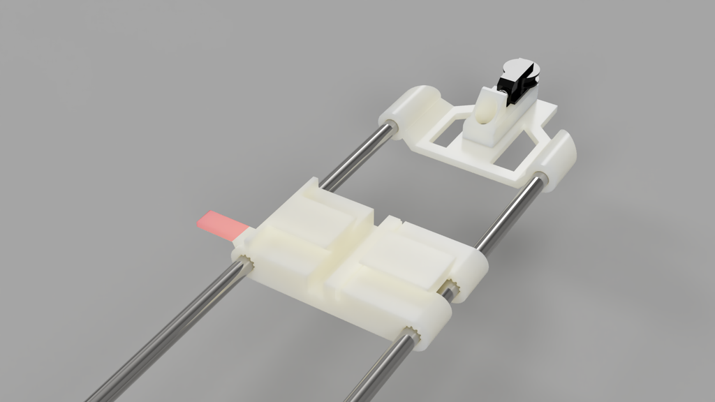
Step 3: Slide the X Axis Shuttle on to the X-axis Rods.
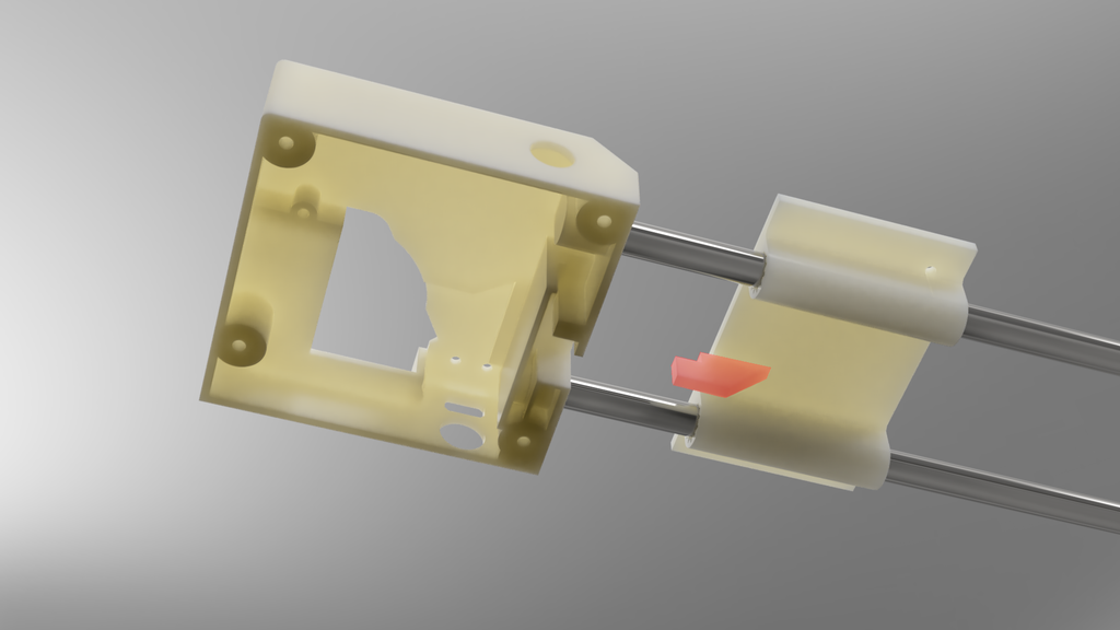
Next, carefully slide the X shuttle onto the metal rods. Take note of the sensor flag, which is indicated in red. Ensure that the flag is facing towards the motor holder assembly. At the base of the motor holder, there is a sensor that is activated by this flag. Proper alignment of the flag is crucial for the sensor to function correctly
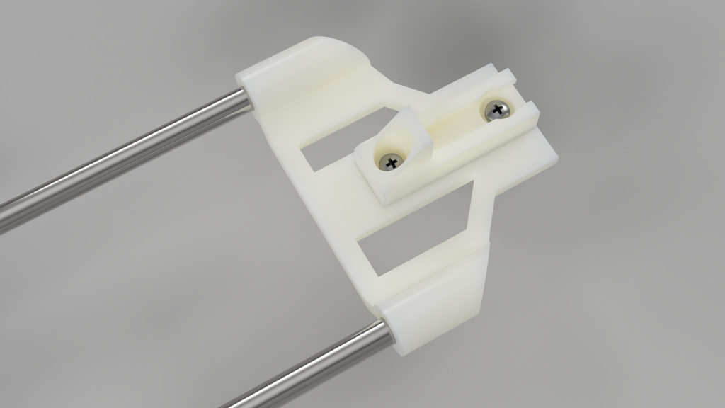
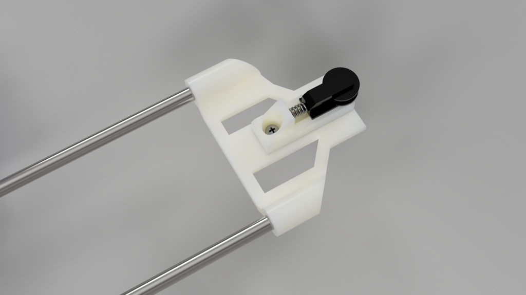
Step 4: Assemble Tensioner
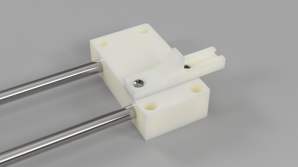
Collect the x-axis tension holder and slide it onto the x-axis rods. Securely attach the x-axis tension spring and pulley holder onto the top of the tension holder using screws. Integrate the spring and tension pulley into the assembly, ensuring they are properly aligned and functioning smoothly
Step 5: Add X Motor and Belt
Position the stepper motor and gearbox on top of the X motor holder assembly. Take the belt, indicated in green, and thread it around the tension pulley, creating a loop. Then, wrap the belt around the motor belt drive gear. Securely fasten the motor into place using screws, ensuring a stable and secure attachment.
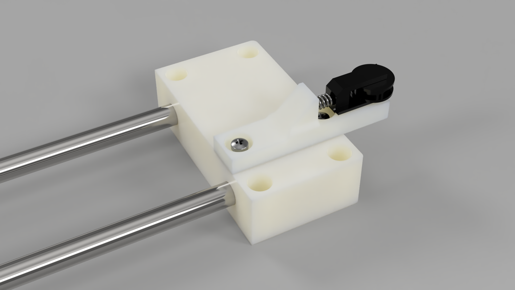
Step 6: Install Home Sensors
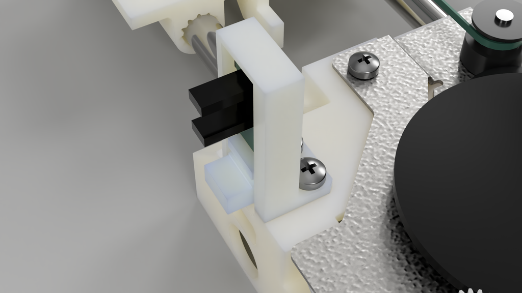
The x-motor holder conveniently houses both the Y and X homing sensors. Insert the Y sensor into the designated Y sensor keeper and securely screw it into place. Additionally, position the X home sensor at the base of the unit, ensuring proper alignment for optimal functionality.
Step 7: This Completes the X-axis Assembly
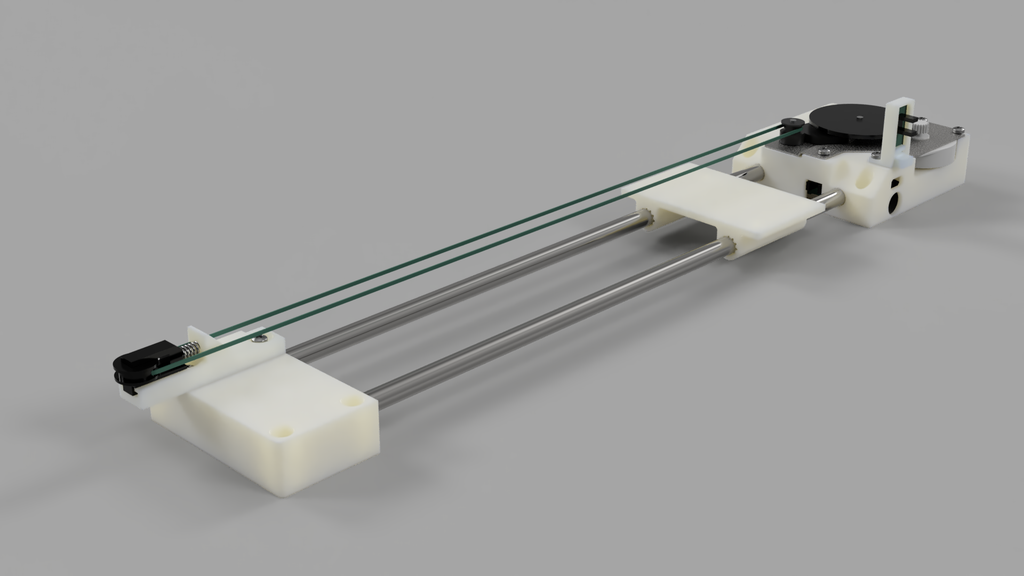
Congratulations you have finished the assembly of the x-axis! Make sure the shuttle moves freely along the shafts.
Step 8: Collect Parts to Assemble X-Axis
5 More Images
To assemble the Y-axis you will need.
- Toothed belt
- Stepper motor and bracket
- 1 tension roller and spring
- 2 x 6mm steel rods
- y-axis shuttle
- y-axis tension holder
- y-axis tension roller and spring
- y-axis motor holder
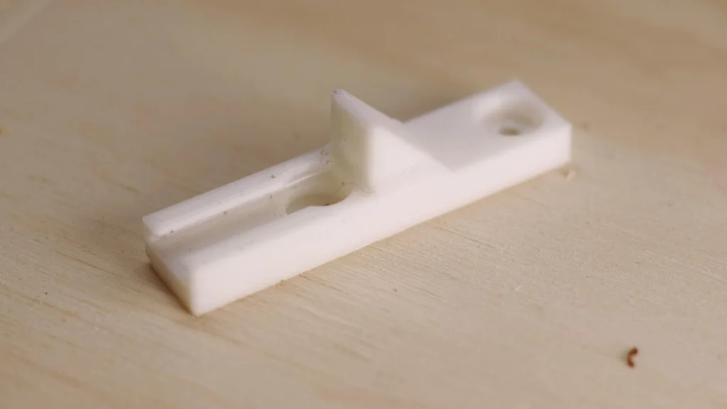
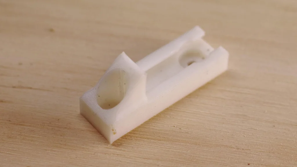
Step 9: Insert Y Rods Into Y Tension Holder
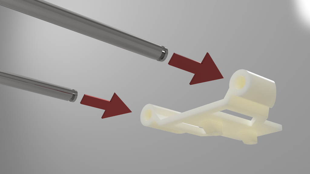
Insert the 6mm rods into the tension holder. It doesn’t matter which end goes into the holder. One end has a slot for a circlip but this has no effect on the operation.
Step 10: Y Tension Assembly
Screw the tension spring holder onto the Y tension holder. Add the spring and tension pully.
Step 11: Install Y Shuttle
Install the Y shuttle on the Y rods. Take note of the homing flag (shown in red). Make sure the shuttle moves freely along the Y rods.
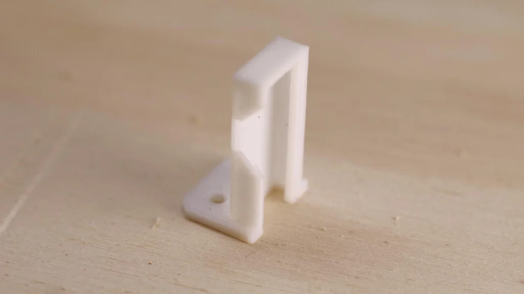
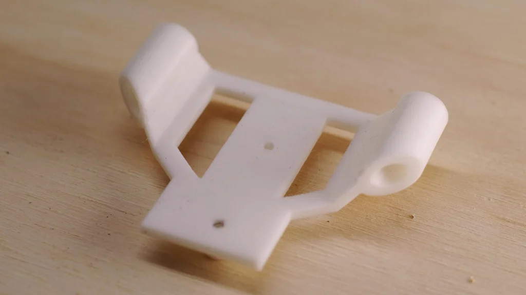
Step 12: Attach Y-motor Holder
Slide the Y-rods into the Y motor holder. Only partially push them in, for now, we need a gap here to put the X-axis belt in the next stage.
Step 13: Marriage of X and Y Axis
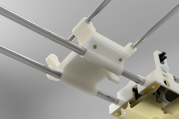
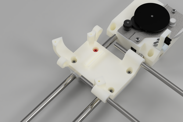
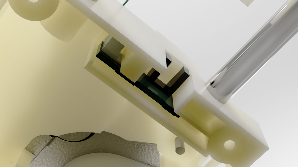
To assemble the Y-axis motor holder, attach it to the X-axis shuttle by aligning the corresponding holes. It’s important to note (as shown in the picture) that the red screw should be a short screw. Using a long screw can result in it inadvertently screwing into the X-axis steel rod, obstructing movement and potentially causing damage to the rod.
Video timestamp
Step 14: Install Belts Into Shuttles

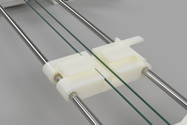
Thread the belt through the serrations in the Y-Axis motor holder, ensuring a snug fit. Although it may be a tight fit, carefully guide the belt through the serrations. Repeat the same process for the Y-Axis shuttle, feeding the belt through the corresponding serrations. In the images, the belt is represented by the color green to aid in visualization.
Step 15: Install Y-Axis Belt

Take one end of the belt and wrap it around the y-axis pulley. Then, guide the other end around the motor drive pulley and ensure it is properly aligned. Proceed to screw the motor into place securely. It’s important to note that the motor assembly is upside down compared to the x-axis configuration.
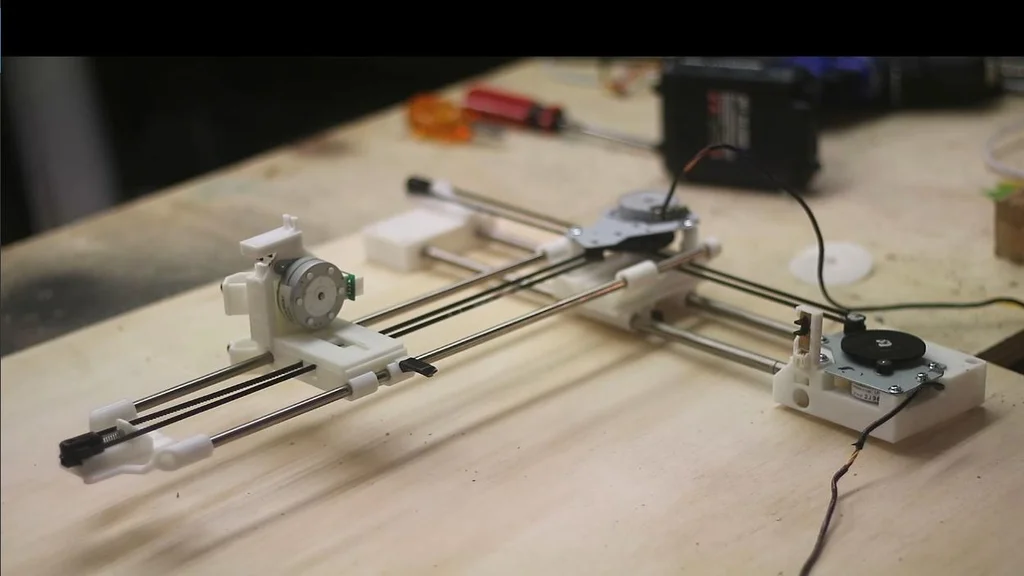
Step 16: Both Axis Complete!
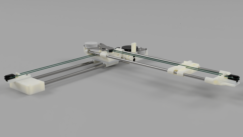
This concludes the construction of the X and Y axis! Turn the motor on each axis to make sure the move each shuttle freely.
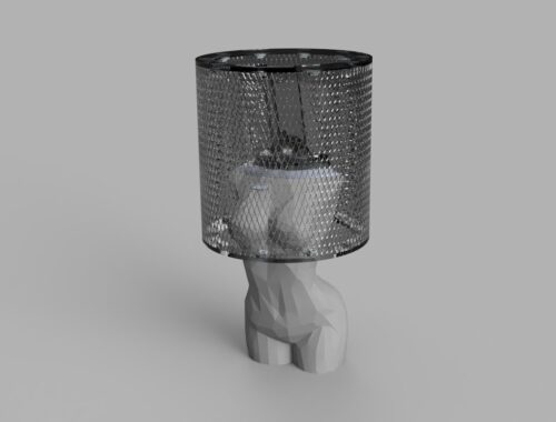
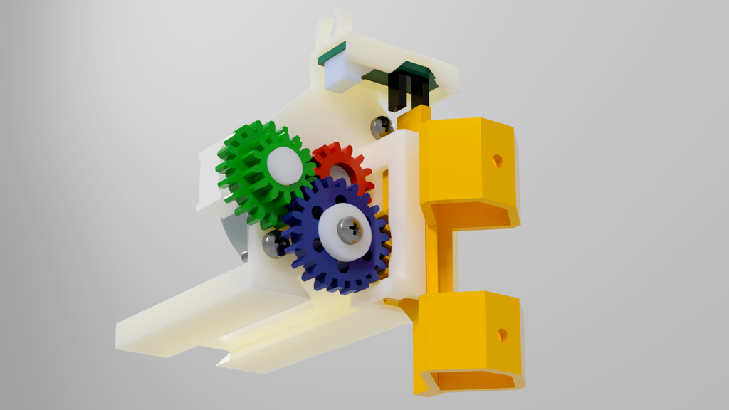
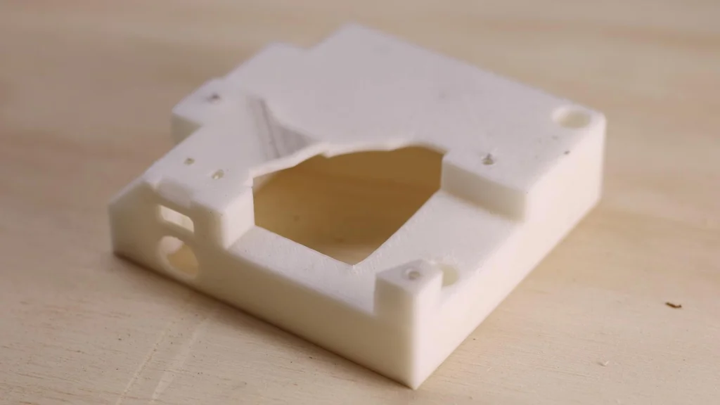
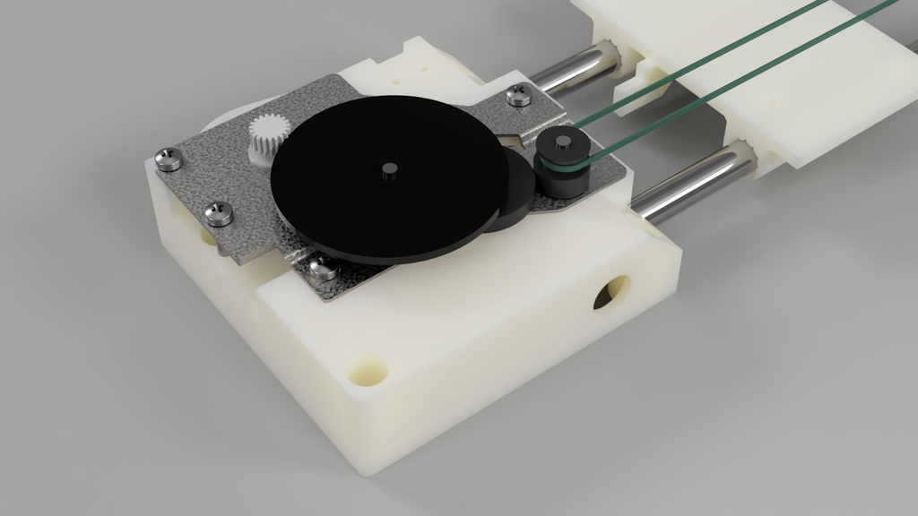
Step 17: Assemble Tool Head

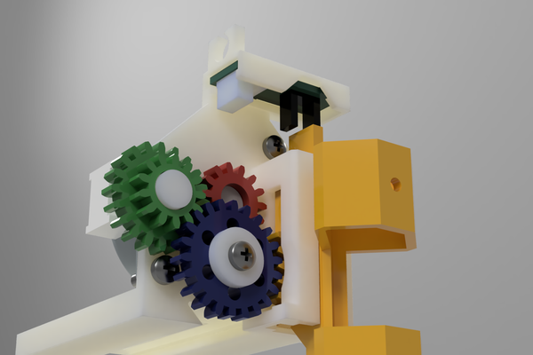
You have the flexibility to create your own tool head for the pen plotter, and it’s straightforward to attach your custom design to the Y-axis shuttle. In my design, I utilized the stepper motor from the printer’s document handler. This choice was made to ensure that all the parts used (excluding the 3D printed components) are sourced from the provided printers.
It’s worth noting that while it is common to use servos to activate the pen, they tend to burn out over time. By using a stepper motor, I aimed to achieve a more reliable mechanism. To simplify the explanation, I have color-coded the gears in the picture.
When attaching the motor, make sure to screw it in with the plug pointing in the direction depicted in the picture. The screws should be inserted from the front side, and you should have a few machine screws with captured washers at your disposal.
- Red gear. This is the gear attached to the stepper motor. The diameter of the motor gear is bigger than the hole in the gear itself. Heat up the gear with a heat gun or similar then push the plastic gear into the stepper gear. This will create a tight fit.
- Push the green gear on with the larger gear to the back.
- Push on the blue gear, and the washer and finally screw this in place.
- The yellow pen holder feeds in from the bottom.
To finish off slide one more sensor across the top of the tool. This is for Z-axis homing.
Step 18: Attach to a Base Board

Now that the machine is fully assembled, the next step is to securely attach it to a flat and sturdy piece of wood. Place the unit on the wood and carefully mark out the hole positions provided on the X-axis motor holder and tensioner holder. Use a drill with a 2mm bit to create holes in each of the marked-out locations.
Finally, fasten the pen plotter onto the designated location by screwing it firmly into place.
Step 19: Conclusion
Congratulations on completing the assembly! If you are already familiar with GRBL, configuring the software side of things should be relatively straightforward for you. However, if you are new to it, you’re in luck because I can guide you through the process in my next tutorial on installing and configuring GRBL you can find this here.