Filament Friend
I was after an easy way to check if my 3D printer was out of filament. You can get filament sensors that detect the filament is missing (run out) but if the filament has broken after the sensor you would never know. All these sensors do really is tell the machine to stop. I would rather know so I could intervene.
There are also sensors that are slightly better and detect the lack of movement so a jam at any position would stop the machine. Again this just stops the machine. I have had little success personally restarting a cold print.
Both sensors require you to feed the filament through the sensor itself introducing a binding point.
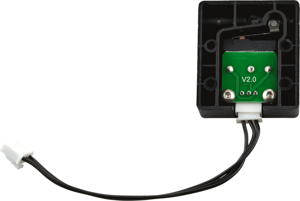
The filament friend
Initially, I designed a tool that used a hall effect sensor on the spool to detect movement. As long as a magnet passed the sensor within a predefined time the tool was happy. If it didn’t turn it would send an email alerting you of the status. A breakdown of that project can be found in the video below.
Unfortunately the same weekend I completed this project Gmail, which I used to send the alert email stopped the service that allowed less secure apps to send emails.
This issue along with the problem of having to add a magnet to every spool led me to try a different approach.
Filament Friend 2.0
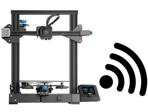
My new version would use more modern push messaging and TOF (time of flight sensor). This little sensor uses a laser to bounce off objects to measure the distance. This change in distance would trigger the “all is ok” part of the code. If the distance remains static for too long an alert would be pushed.
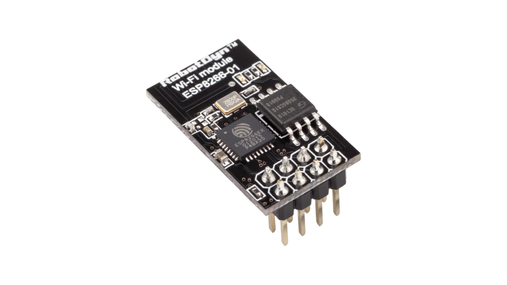
In my original Filament Friend, I used an ESP-01 which is a tiny Arduino-compatible MCU with wifi. The big issue with this device is the lack of easy debugging.
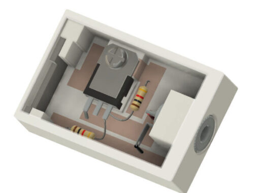
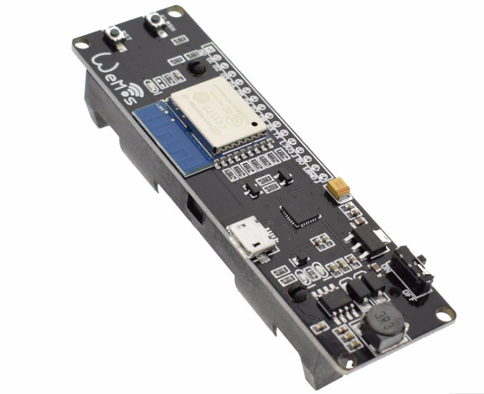
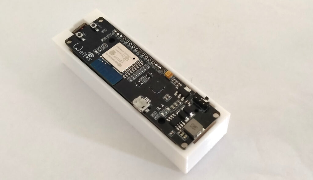
Further research found a cool little MCU dev board with a built-in 18650 battery charger and holder. This would have its own power supply or USB power, multiple inputs and outputs, and also debugging while still being small in size.
Once I had decided on this unit it was down to designing the case it was to go into. My usual goto for STL and step files Grabcad came up empty with a version of this particular board so I had to design one of these from the ground up to start with. My search did find a few similar including one with an OLED screen which would be cool for a project.
Once the board was mocked up it was down to designing a case around it. For this, I needed to consider the TOF sensor.
Time of flight sensor.
Time of flight sensors as mentioned before shoots out a laser and the time it takes for the light to reflect back to the unit is used to calculate the distance, or, the time of flight.
The unit I am using is the VL53LOX. There seem to be a few variations of break-out boards for this sensor and I opted for the smallest.
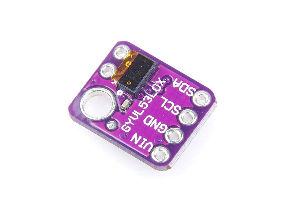
Getting this up and running was pretty simple it uses the I2C bus and there is no shortage of documentation on getting I2C to work with Arduino.
What I found with the sensor (this version any) is that the readings vary wildly. Or the measured values can swing up to 10mm depending on the surface. Even when both the object and the sensor are static I would get readings from 100-110mm. Deciding the output seems almost analog in nature I incorporated the smoothing sketch found on the Arduino website and sketch examples. This seemed to tame the beast to a somewhat usable solution.
With the TOF now in a more stable position, I may still need to attach something to the spool. I could now go ahead and design the case to hold it all together.
Getting the message out.
In my first version of the Filament Friend, I used Gmail to message any alerts. Coincidently Gmail killed off email from less secure apps so that solution was not really available anymore.
I was really keen on a push message system that wasn’t too complicated and accessible to everyone. In the past I had used IFTTT in my Turn on your lights with Google assitant – IFTTT – MQTT – WLED video. Here I used Google assistance to turn on my RGB trampoline.
This looked like the solution again where you would only need to install the IFTTT app, configure the service in IFTTT, and the Arduino code for push messaging to work. I found this great tutorial here to get me up and running.
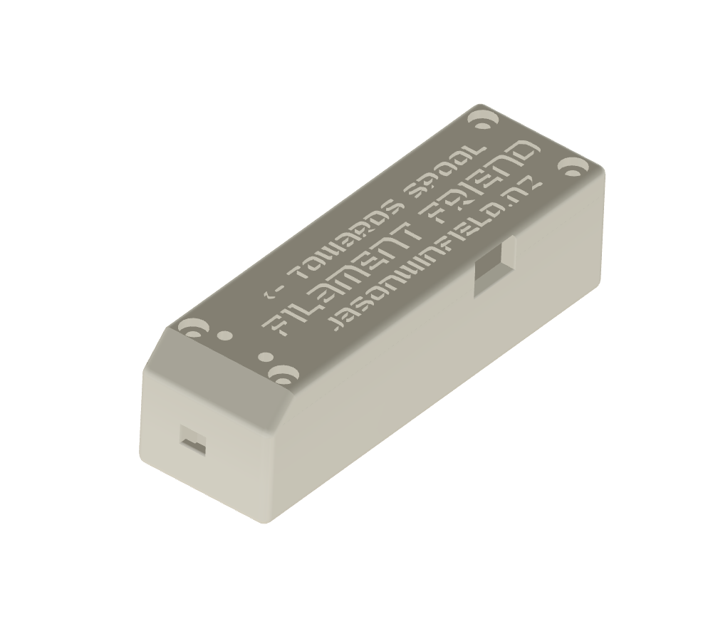
Case design.
A few simple mockups to start with got a self-contained unit. I put a small hole in one end for the sensor to “look out”. The whole unit fits in this case nicely. The tool itself would just need to sit near the spool (around 100mm) this could just be the top of the gantry. I will have a few different lid designs so you could even use a GoPro mount as these cameras have a plethora of mounting options.
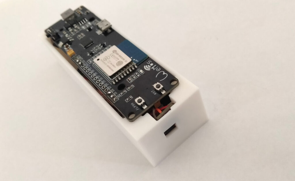
This design is a bit rough and ready for the POC. Later designs, if everything works out will look a bit tidier.
First tests
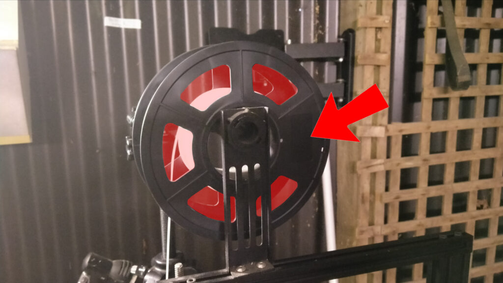
With the case designed up and some rough code cobbled together, I set a print running to see what would happen. The spool I have on the printer at the moment is almost empty so I placed the tool so it could see through the gaps in the spool.
With the tool on the back, I fired it forwards and recorded the readings with some debug output. I then graphed the output below.
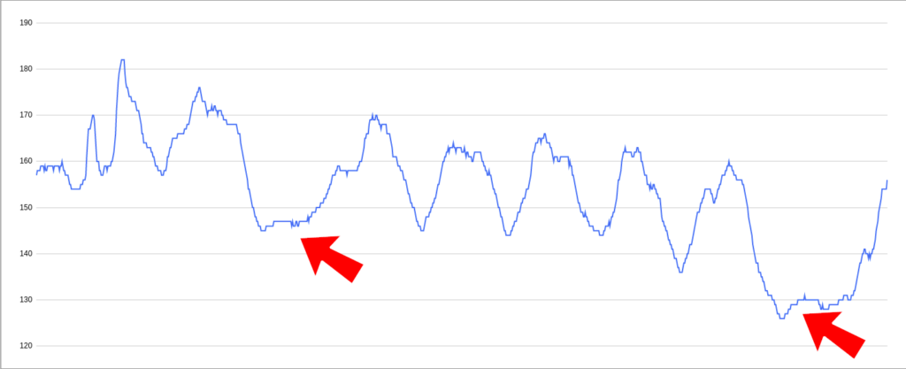
The data above is from a full rotation, the arrows are pointing towards the flat spot pointed out on the spool. You can clearly see the five gaps in the spool also. This sample was over around a 16min period.
I expect the moving downwards across the sample is due to the spool moving back and forward.
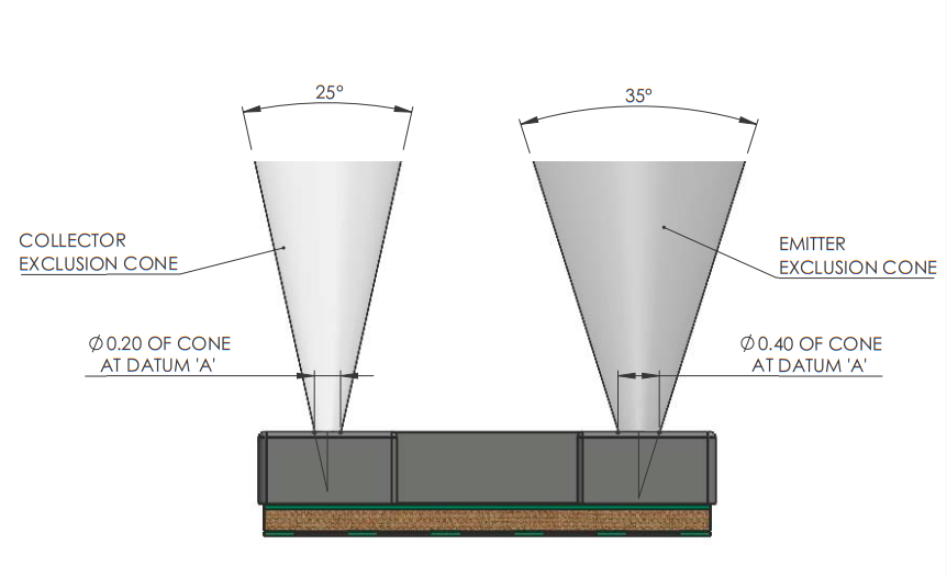
I was under the impression that if the laser was shooting through the spool the distance would shoot up to meters as in theory there is nothing to bounce off but the other wall of my shed. The data sheet shows that the sensor housing requires a pretty wide viewing angle so I suspect this is the actual viewing angle.
Of course the further you have the sensor from the spool the less likely it is to detect the gaps in the spool as the focus area will encompass the spool itself.
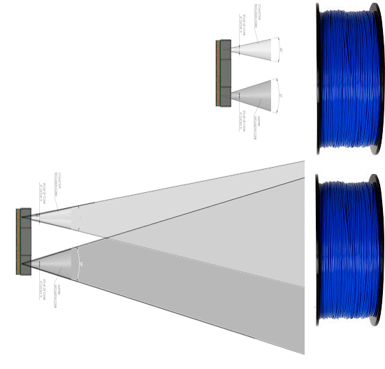
The intention was always to have the tool at a maximum of 100mm.
I can see the tool can detect movement but the test will be to see if it can detect no movement and what kind of variation we can expect in this situation.
Detecting a jam
This is all a bit pointless if the sensor fails to detect a jam. I stopped the spool and again logged the output and plotted the result below.
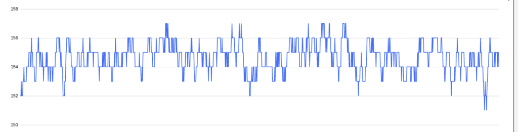
This looks bad but it is actually pretty good when you see the scale the swing is between 151-157mm. While static and looking through a gap in the spool. If I place the tool in front of the spool with no gap the variation is just a couple of millimeters.
Overlaying the moving spool with a static spool the difference is clear.
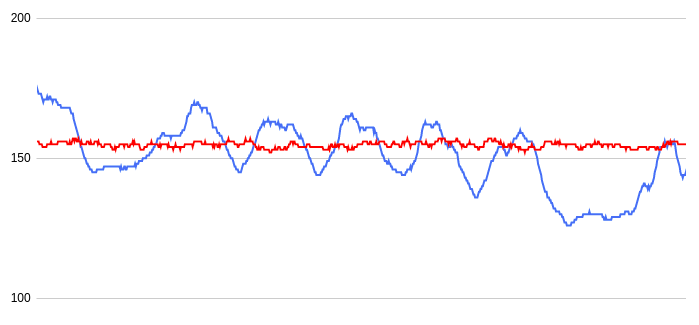
With this spool “profile”, we can configure our minimum movement amount and time we should wait for a change. This is just for this spool type and is also almost empty. I will have to think of something a bit more universal.
For now, I think I have something to work with so I will start on the IFTTT integration and test the unit in full production.
To keep up with developments subscribe to my YouTube channel:

No STLS or sketches to release yet.