LP-E17 Mains adapter
In this project, I needed a mains adapter for my EOS-M3 camera. Filming videos chews up a lot of battery. Going out to do some shooting when I finally find the time and to find the battery is dead is a total pain. With a mains adapter, I never need to worry about the state of the battery.
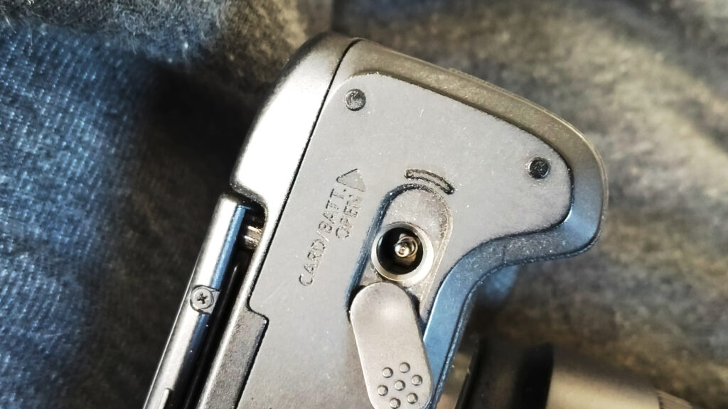
Getting power in.
Even though I have owned this camera for 4-5 years I didn’t realize that it had a hole designed in the battery cover for a power adapter. A real “life hack” moment. The slider for opening the cover moves to the side to reveal the charging hole.
The next challenge was to create the file in fusion360. The battery itself is just a brick but the contacts need to line up perfectly otherwise no power would be applied to the terminals.
The battery itself has an odd voltage of 7.2V which isn’t something you will easily find in the local shops. 3.3V, 5V, and 12V are the norm so I would need to create some sort of regulation to get the correct voltage and supply sufficient current.
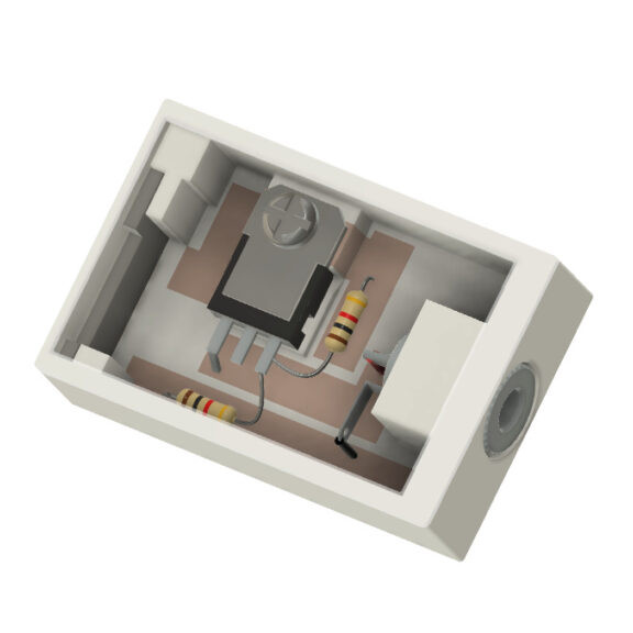
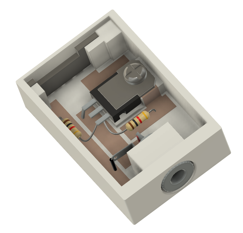
As 7.2V regulators arent really available I opted for an LM-317 variable regulator.
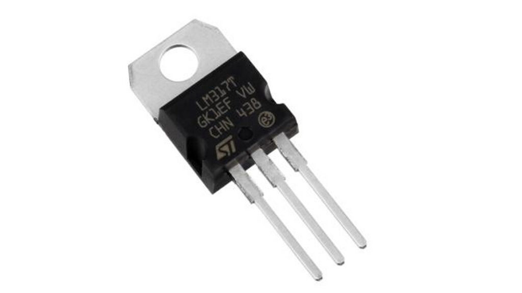
This regulator just needs a couple of resistors to configure the supply voltage and can handle up 1.5A of power so this project is well within its wheelhouse.
A quick calculation using an online calculator found the resistors required would be 1k and 4k7. Something easily found in any electronics spares box.
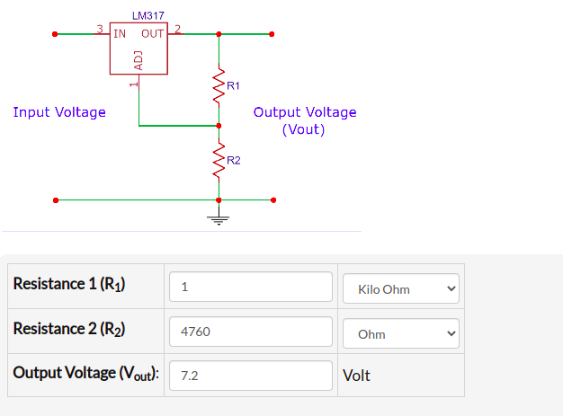
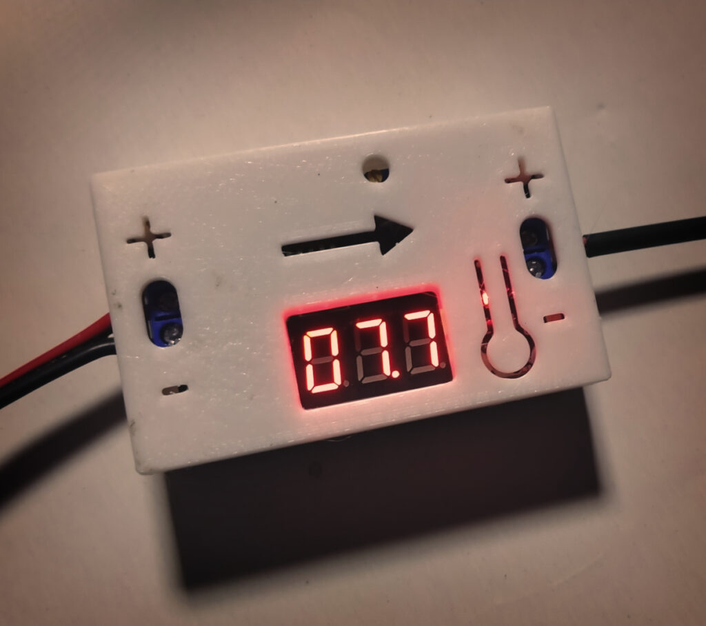
With the circuit configured I found the voltage to be around 7.3 volts. Taking into account the resistor tolerances this was fine. The battery itself provided 8V so this extra .1 was not going to be much of an issue.
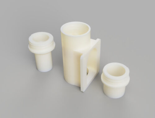
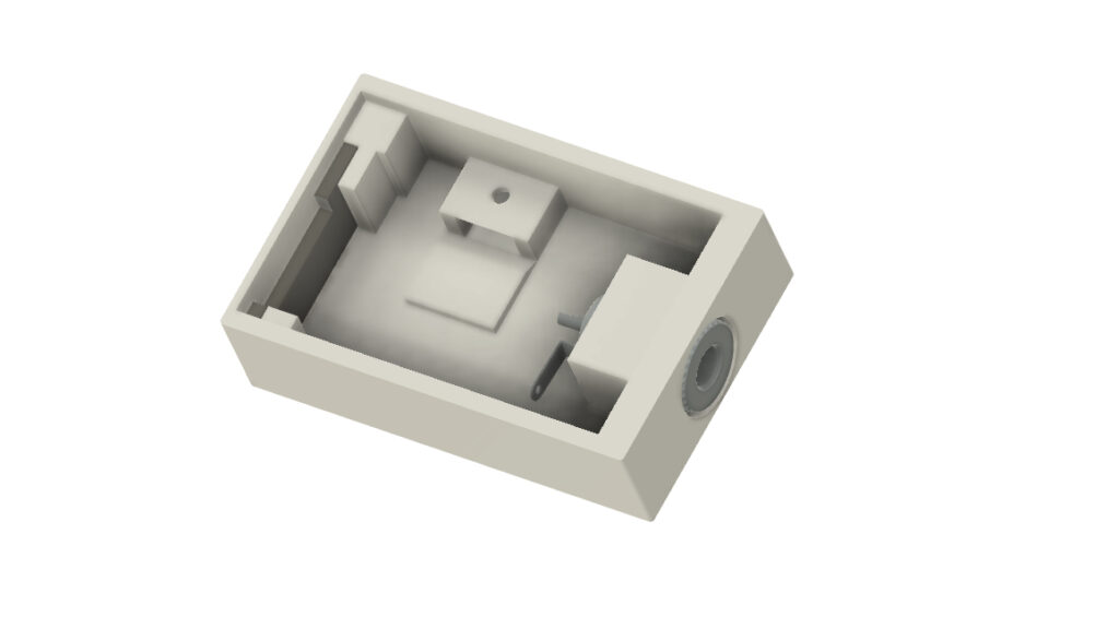
With the circuit completed, I set about designing the battery case itself.
First design
The design required a DC power socket. A panel mount version wouldn’t really do here as the locking nut would be wider than the case itself. I opted rather to use a regular cable end adapter and use the battery case as the screw-in point rather than the usual cable cover.
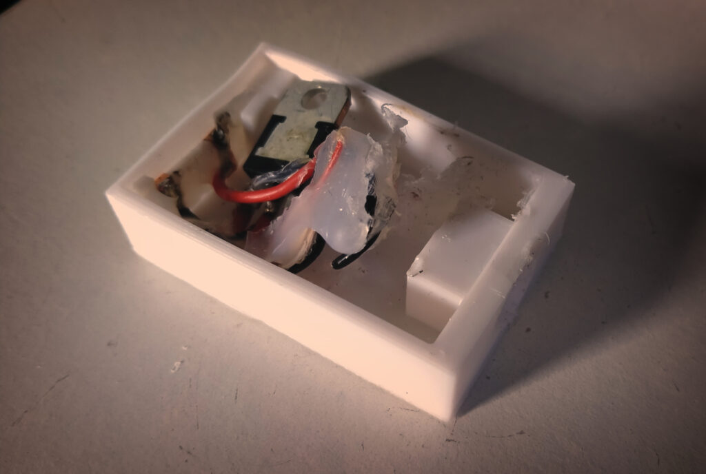
Once this was completed it was a case of adding the rest of the components and testing it out on the camera.
Houston we have a problem
All things assembled I put the battery into the camera and fired it up. Expecting a litany of complaints from the camera about being subjected to nonfactory parts I was pleasantly surprised with no feedback at all from the camera. As far as it was concerned it seemed as though everything was normal.
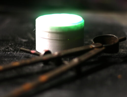
Time to try it out.
The long-term goal here is to have high-quality timelapse videos of 3D prints. These take time obviously so the camera needs to work without an issue for a few hours at least.
I started a Benchy print and crossed my fingers. I found in about 15-20mins the camera had died? To investigate further I decided to pull the battery case out and have a look, except I couldn’t. The battery case glued itself in place.
I used a hot glue gun to hold the components in place. Although the heat generated by the regulator wasn’t hot enough to melt the PLA it was enough to melt the hot glue. This then cooled and glued itself to the inside of the camera!
Fearing all was lost anyway I used brute force and ignorance to rip the battery out with long-nose pliers.
Fortunately, the camera survived the experience and being a sucker for punishment I persevered with version 2.
Nope, that ain’t going to work either.
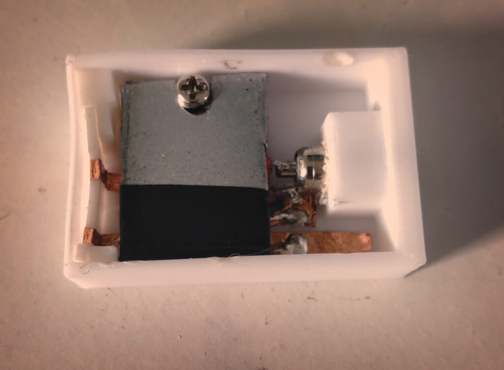
Taking what I didn’t already like from the first version I moved to copper tape throughout the battery and added even more heatsinks.

The regulator now had two pretty thick bits of metal screwed down to absorb the heat from the regulator. It was now time for attempt two.
Although this did last longer the heat from the regulator softened the PLA sufficiently that the spring contacts pushed the contacts in the holder away and eventually dropped out of reach altogether.
Jackpot
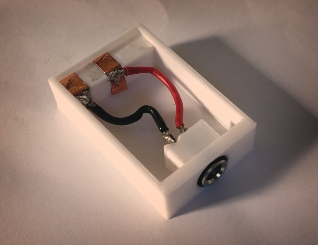
I wasn’t sure if it was just the heat in the camera or that along with the regulator softening the PLA. As a last-ditch effort, I moved all the electronics out of the case and just had the wires from the DC connector to the battery terminals.
I purchased a cheap step-down voltage converter and printed a case for it. This would supply the voltage required to power the camera.
The case couldn’t be simpler or cheaper now with just the DC connector some wires and the copper tape.
“The best part is no part. The best process is no process. It weighs nothing. Costs nothing. Can’t go wrong.”
Elon Musk
This ended up being the working design. There is no heat generated at all from the camera after hours of use so the heat was just purely the regulator.
Conclusion
If you would like to try and make the internal regulated version here is the wiring diagram.
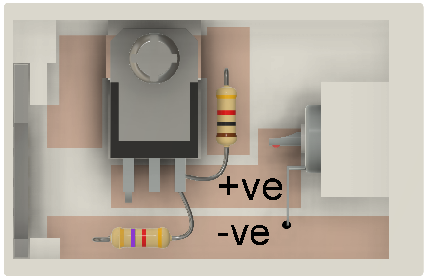
I don’t show it in this diagram but you would run copper tape up to the connectors to the left. Note that the copper tape goes under the regulator. This is required as the regulated voltage is collected from the heatsink. The center pin of the regulator is NOT connected. The input voltage pint is soldered directly to the +ve tape.
When putting copper tape down you will need to solder each strip together as the sticky part of the tape acts as an insulator.
For the non-regulated version the -ve side is to the edge of the battery. If you already have a Canon LP-E17 it should show the markings to confirm.
If you would like to make the same adapter the STL files are below along with the buck converter used and connector.
Step down power buck converter: https://jasonwinfield.nz/product/step-down-power-supply/
Custom Camera Firmware can be found here: https://chdk.fandom.com/wiki/CHDK
STLS: https://cults3d.com/en/3d-model/gadget/lp-e17-dc-power-adapter

Getting started with ESP-01 and WLED