Sensing spider
Halloween is coming and spiders are perfect for creating a good scare. This project can be either 3D printed or made from wood. A great and challenging introduction to Arduino that demonstrates a practical use of multiple inputs and outputs.
Using a PIR sensor our target is automatically detected and our spider deployed rapidly for the perfect fright.
Check the video links if you get stuck on a step these are timestamped so should go directly to the place you are at.
Code examples
Here are the code examples shown for each sensor in my build video.
Motor code
const int motorFWD = 5; //UNO
const int motorREV = 6; //UNO

void setup() {
  // put your setup code here, to run once:
  pinMode(motorFWD, OUTPUT);
  pinMode(motorREV, OUTPUT);
}

void loop() {
  // put your main code here, to run repeatedly:
digitalWrite(motorFWD, 1);
digitalWrite(motorREV, 1);
}
PIR Code
const int PIRpin = 2;
const int LEDpin =13;
int PIRstate = 0;

void setup() {
  pinMode(LEDpin, OUTPUT);
  pinMode(PIRpin, INPUT);
}

void loop() {
   PIRstate = digitalRead(PIRpin);

  if (PIRstate == HIGH ) {
    digitalWrite(LEDpin, HIGH);
    delay(1000);
  }
digitalWrite(LEDpin, LOW);
}
Switch code
/*
  Button

  Turns on and off a light emitting diode(LED) connected to digital pin 13,
  when pressing a pushbutton attached to pin 2.

  The circuit:
  - LED attached from pin 13 to ground through 220 ohm resistor
  - pushbutton attached to pin 2 from +5V
  - 10K resistor attached to pin 2 from ground

  - Note: on most Arduinos there is already an LED on the board
    attached to pin 13.

  created 2005
  by DojoDave <http://www.0j0.org>
  modified 30 Aug 2011
  by Tom Igoe

  This example code is in the public domain.

  https://www.arduino.cc/en/Tutorial/BuiltInExamples/Button
*/

// constants won't change. They're used here to set pin numbers:
const int buttonPin = 3;     // the number of the pushbutton pin
const int ledPin =  13;      // the number of the LED pin

// variables will change:
int buttonState = 0;         // variable for reading the pushbutton status

void setup() {
  // initialize the LED pin as an output:
  pinMode(ledPin, OUTPUT);
  // initialize the pushbutton pin as an input:
  pinMode(buttonPin, INPUT);
}

void loop() {
  // read the state of the pushbutton value:
  buttonState = digitalRead(buttonPin);

  // check if the pushbutton is pressed. If it is, the buttonState is HIGH:
  if (buttonState == HIGH) {
    // turn LED on:
    digitalWrite(ledPin, HIGH);
  } else {
    // turn LED off:
    digitalWrite(ledPin, LOW);
  }
}
Supplies
1 × DC motor
1 × Arduino Uno
1 × 9v Battery and snap connector
1 × PLA or ABS for 3D print
6 × Screws 6x3mm self-tapping
2 × Scews 16x2mm
1 x Screw 50x3mm
1 × Cotton spool
1 × Toy spider approx 50-60mm wide or 3D printAdd TipAsk QuestionCommentDownload
Step 1: Print STLS

STLs can be found here.
Print the STL files. The main chassis should not need support but I suggest you set the area around screw holes to 100% infill to prevent the filament splitting. If you are printing on an FDM printer, print the spider upside down. The spool will need support.
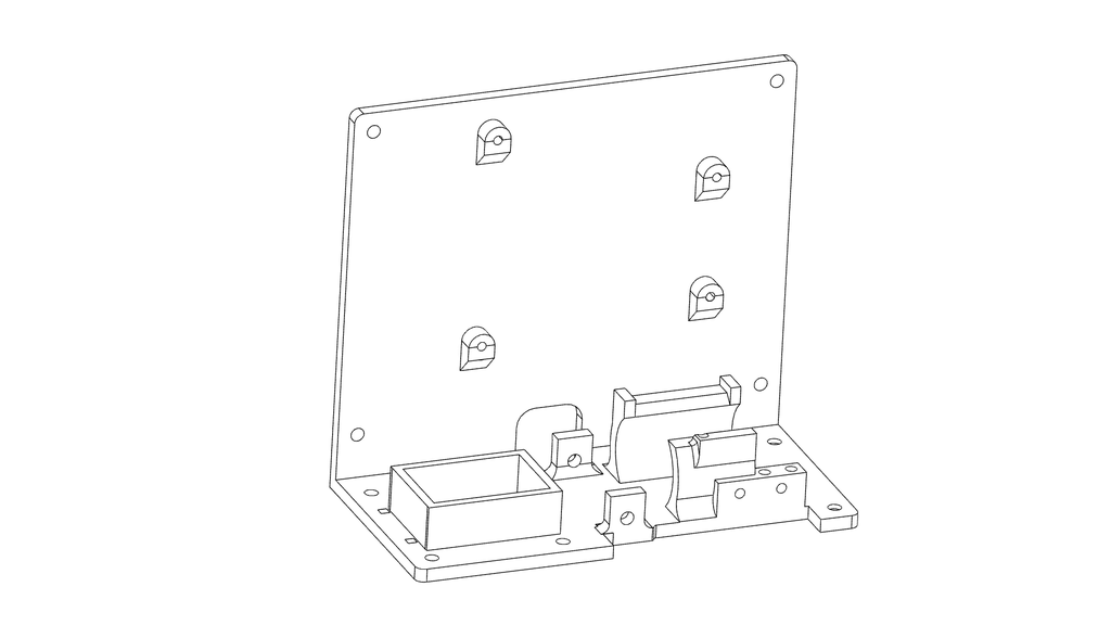
Step 2: Install Arduino

Screw the Arduino UNO into place using 4 6×3 screws. More details in the video here
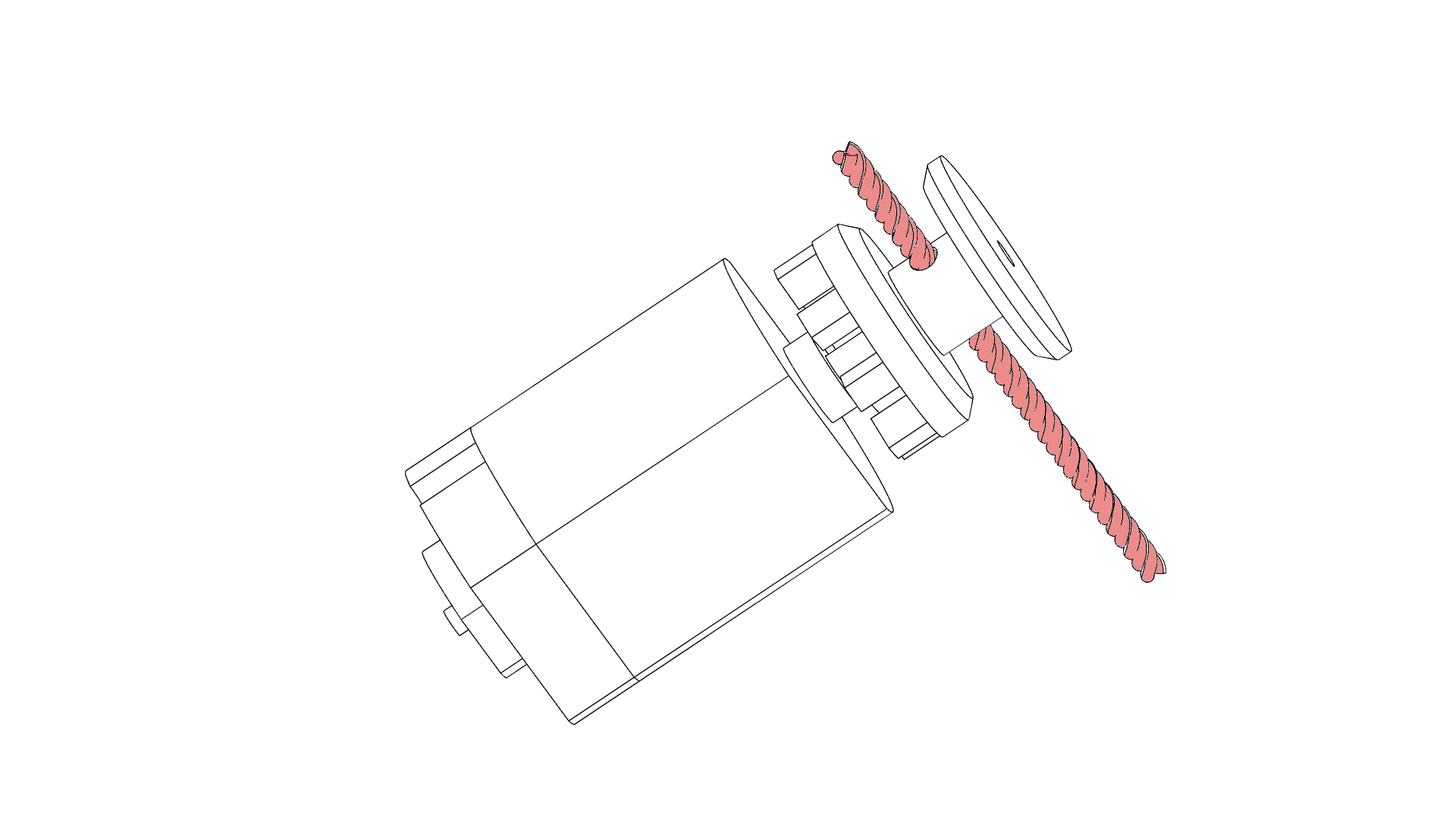
Step 3: Motor Installation
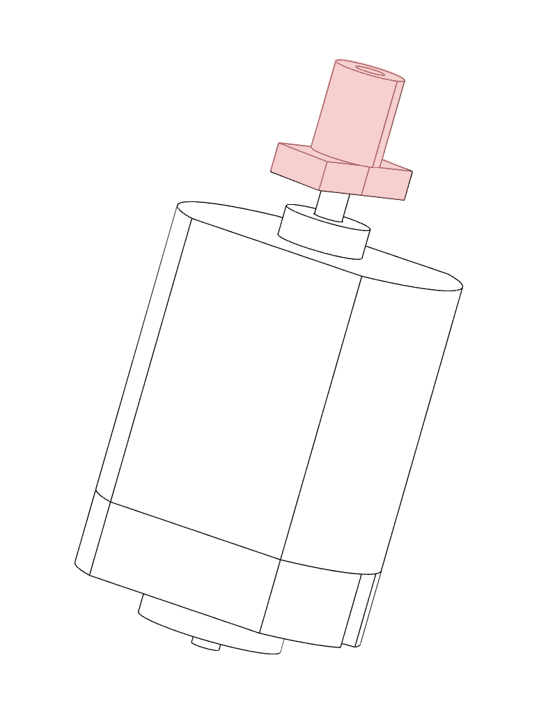
Using a small hammer tap the drive boss onto the shaft of the motor. More details on the video here
Step 4: Slide the Motor Into the Base of the Chassis.

Slide the motor into the base of the chassis.
Step 5: Install Microswitch
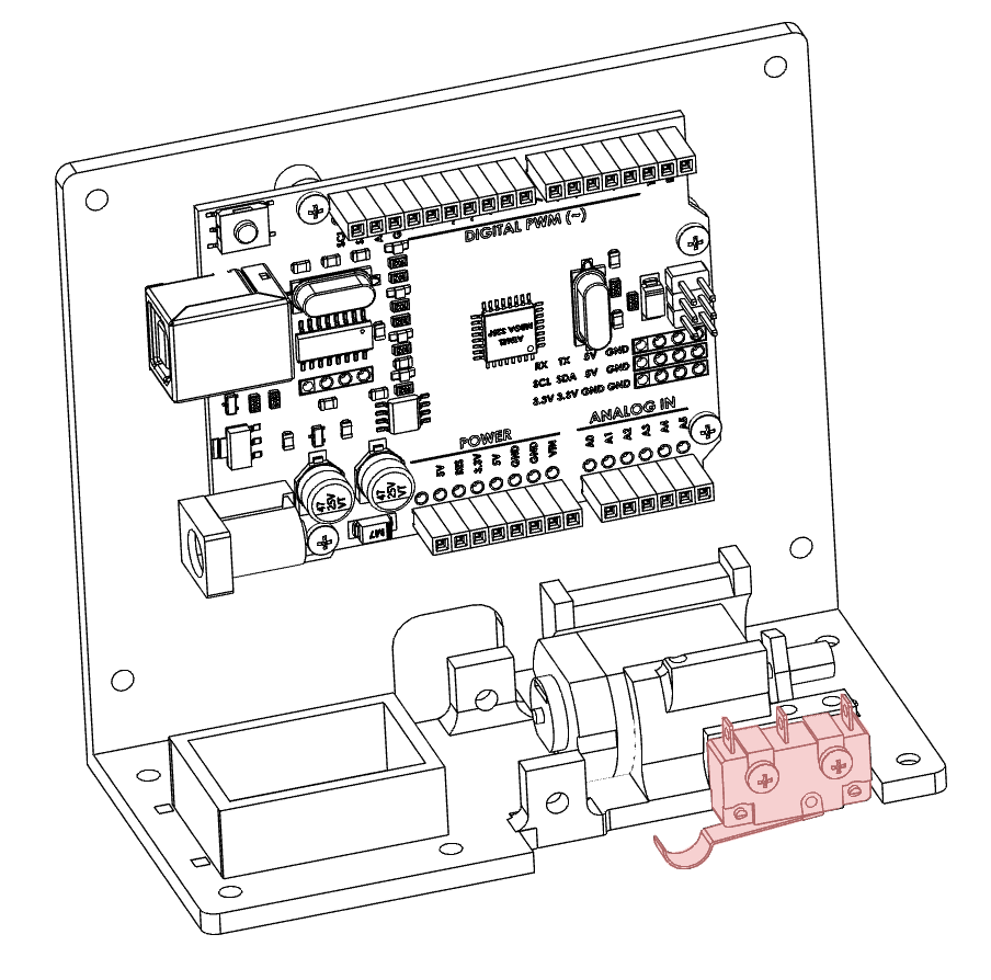
The microswitch is installed into the front of the chassis with the two 2x16mm screws. One screw is fully tightened while the other is tightened just enough to hold the motor in place. More details are in the video here.
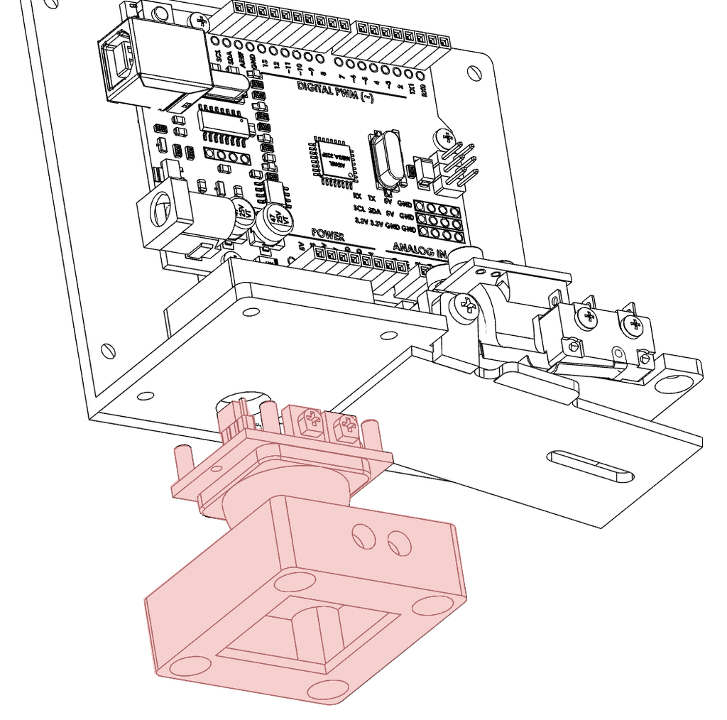
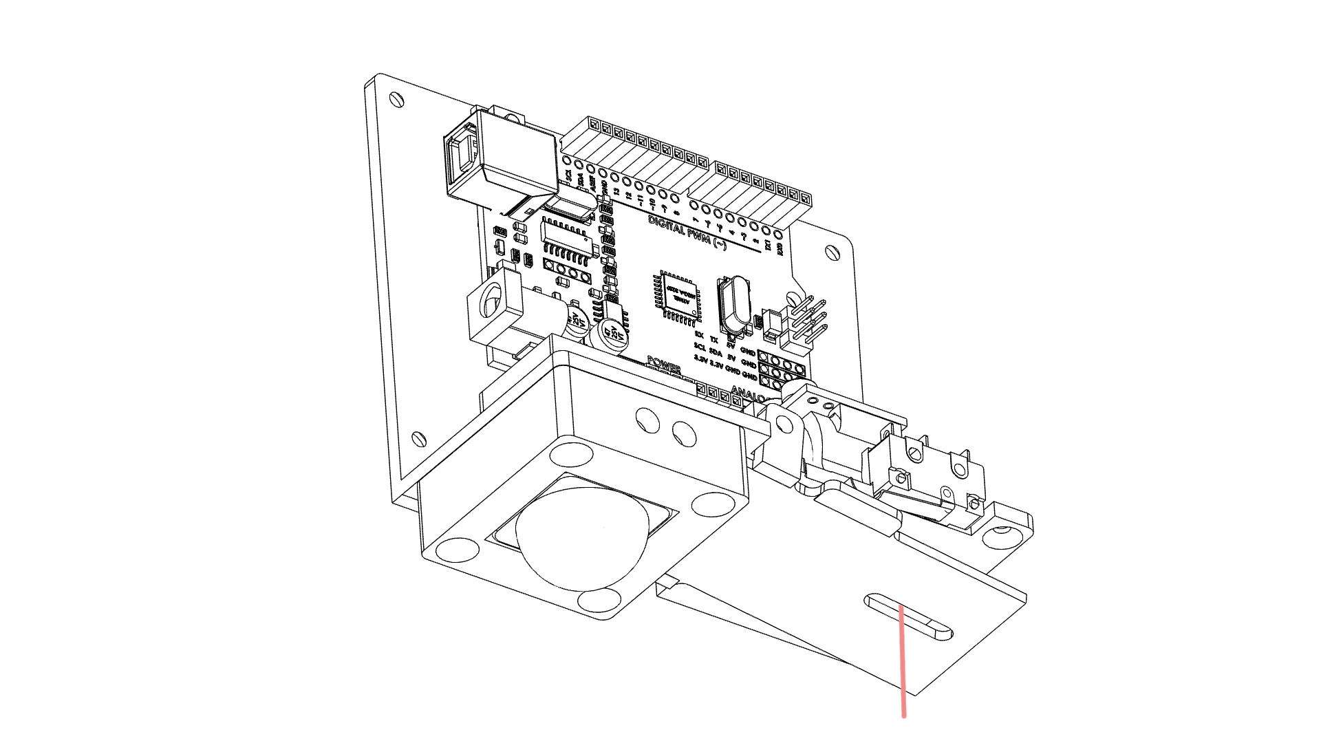
Step 6: Install Limit Paddle

The limit paddle stops the spider from driving too far up. The paddle is held in place by one 3×50 screw which runs across the chassis. The paddle should be able to move freely and without obstruction. When the paddle moves it should activate the microswitch. You should hear an audible click when the paddle is moved upwards.
Step 7: Wire Motor Controller.

Prepare the motor driver for installation. The motor driver can drive two motors but we only need to use one for this project. Add a length of wire to each of the MOTOR A outputs. These will eventually be connected to our motor. Add a length of wire to the + and – terminals of the board. Then a length of wire to IN1 and IN2. Put a header pin on all but the motor wires to make installation easier later on.
Step 8: Install the Motor Driver Board

The motor driver board sits on top of the motor. There is a location for one screw and the rear of the board sits between two uprights. More details can be found here in the video.
Step 9: Wire the PIR Sensor
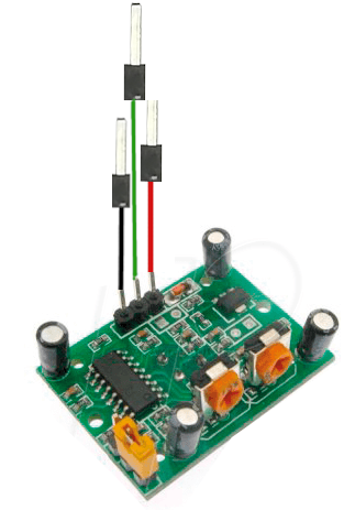
The PIR sensor has 3 connections Ground, 5V, and the signal wire. Attach a length of wire to each contact as shown below.
Step 10: Install the PIR Sensor

Thread the wires from the PIR sensor through the hole in the base of the chassis next to the battery holder. Place the sensor in the sensor holder with the adjustment screws facing the holes in the sensor holder. Screw the sensor and holder into place. More details are in the video here.
Step 11: Thread the Spool
Thread your spider web (cotton) through the hole in the chassis and paddle below where the spool will go.
Then thread the cotton through the hole in the spool. You should be able to slide the spool over the drive boss which will keep the cotton in place.
Attach your spider to the other end of the thread.
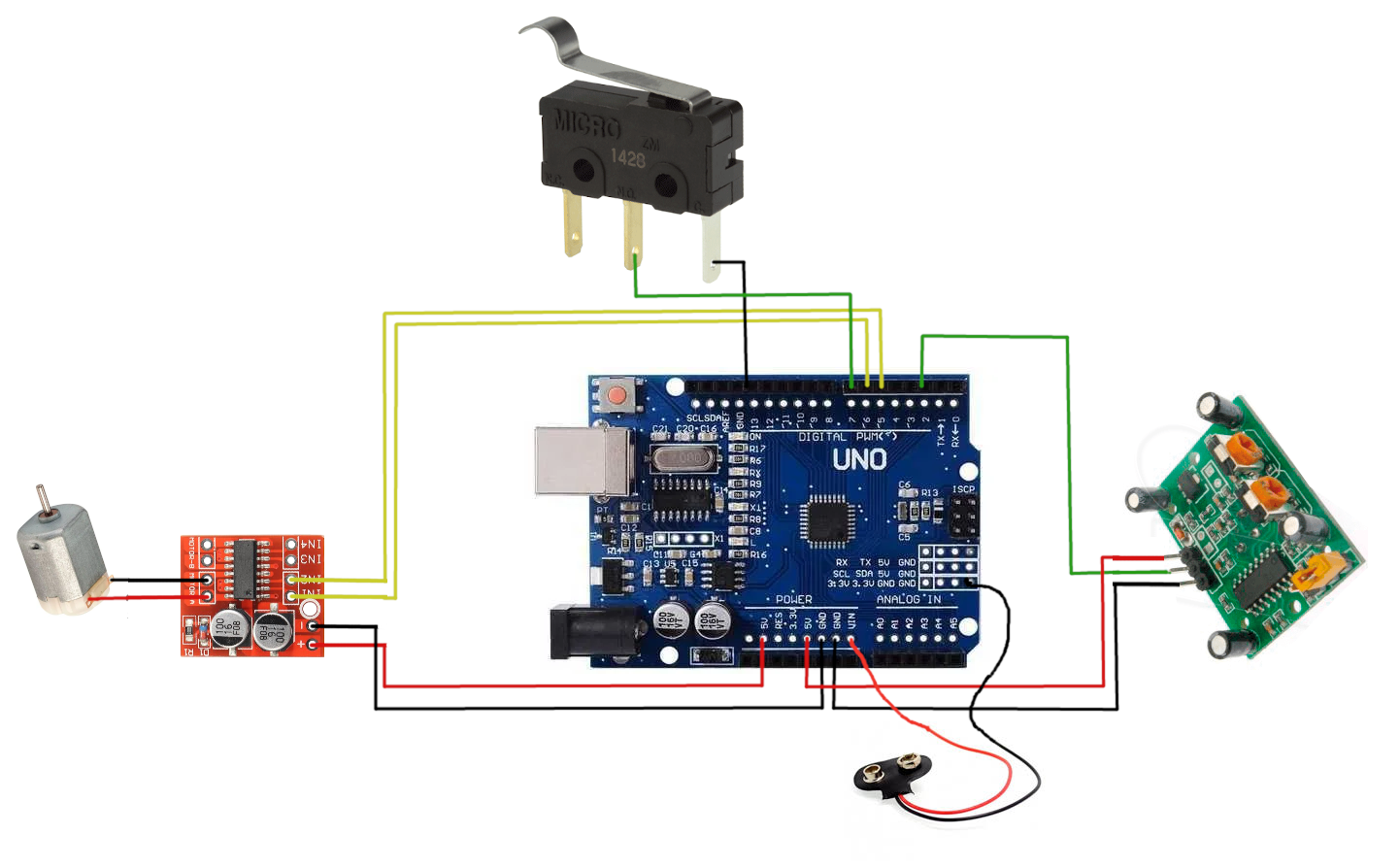
Step 12: Wiring
Following the diagram below pay careful attention to the polarity (red and black wires), The colour of the signal wires isn’t important just use what you have laying around. The most important thing is to make sure you have the battery going to VIN, not to 5V otherwise you will cook your Arduino.
Step 13: Upload Sketch
Copy and paste the following code into your Arduino IDE, no extra libraries are required. I am not a programmer by trade but this code seems to do the job. See if you can improve it. An interrupt would be a better choice than the do loop I have used for example.
<!-- wp:preformatted -->
<pre class="wp-block-preformatted">// constants won't change. They're used here to set pin numbers:
const int PIRpin = 2;
//const int LEDpin =1; //digispark
const int LEDpin =13; //UNO
const int limitPin = 7; // the number of the pushbutton pin
//const int motorFWD = 0; //digispark
// const int motorREV = 4; //digispark
const int motorFWD = 5; //UNO
const int motorREV = 6; //UNO
const int frightDelay = 10000; //delay between actions
const int acceleration = 25; //how fast the motor starts to int acceleration delay in ms
// variables will change:
int limitState = 1; // variable for reading the pushbutton status
int PIRstate = 0;
int MOTdirection = 1;
int PWMValue = 200; // starting PWM value
void setup() {
// initialize the LED pin as an output:
pinMode(LEDpin, OUTPUT);
pinMode(PIRpin, INPUT);
pinMode(motorFWD, OUTPUT);
pinMode(motorREV, OUTPUT);
pinMode(limitPin, INPUT_PULLUP);
}
void loop() {
PIRstate = digitalRead(PIRpin);
if (PIRstate == HIGH ) {
PWMValue=200;
digitalWrite(LEDpin, HIGH);
do
{
limitState = digitalRead(limitPin);
driveMotor();
} while (limitState != 0); //state is 1 button is not activated
if (MOTdirection ==0){MOTdirection = 1;} else { MOTdirection = 0;}
stopMotor();
delay(500);
lockMotor();
delay(1000);
stopMotor();
delay(frightDelay);
}
digitalWrite(LEDpin, LOW);
}
void driveMotor(){
if (PWMValue < 255){++PWMValue;}
delay(acceleration);
if (MOTdirection ==1)
{
analogWrite(motorFWD, PWMValue);
analogWrite(motorREV, 0);
}
else
{
analogWrite(motorFWD, 0);
analogWrite(motorREV, PWMValue);
}
}
void stopMotor(){
analogWrite(motorFWD, 0);
analogWrite(motorREV, 0);
}
void lockMotor(){
digitalWrite(motorFWD, 1);
digitalWrite(motorREV, 1);
}</pre>
<!-- /wp:preformatted -->
<!-- wp:paragraph -->
<p></p>
<!-- /wp:paragraph -->Step 14: Testing
Once you upload the code the motor will probably try and drive immediately as the PIR is high when it turns on. For testing, I suggest you attach the unit to the roof somewhere to prevent the tangling of the cotton. Check my testing in the video for some tips.
Depending on the length of your thread, the weight of the spider, and the speed of the motor it might take a bit of tweaking to get the spider to drop and return to the full length of the thread. I suggest you check the principle of operation here: to get a goof idea of what is happening.
There are three main variables you can change.
frighdelay
This is the time the spider waits between dropping. This value is milliseconds so 10000 is 10 seconds. Increase or decrease to your desire.
PWMvalue
If the motor starts spinning at full speed the thread will double up on itself and the spider will drop a very short distance. The value is between 0 and 255. If you find the spider does not always fully unravel LOWERING this value makes the motor start slower. Keep increasing this value until you don’t have the cotton binding on itself. If the speed for the whole journey is too slow the spider will not have enough momentum to trigger the limit switch at the end of the run.
Acceleration
This is how fast the Arduino will increase the speed. This is in milliseconds. Tweaking between this value and the PWMvalue you should be able to find the sweet spot for your spider.
Notes about your spider
Not all spiders are created equal. The weight and size of your spider will greatly affect how the project behaves. If your spider is too heavy it will unravel the web due to its weight. If it is too light it might not activate the limit switch. In my testing, the spider weighed around 6 grams.
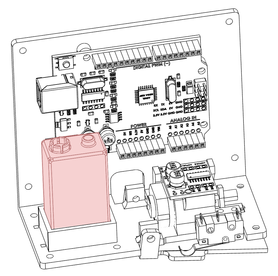
Step 15: Install Battery and Scare Away!
The 9V battery sits in the front of the unit in the box supplied. Once you have all your spiedy tweaking nailed in attach the unit above a doorway and enjoy the scares!
